
Eratherm İzolasyon A.Ş.
Capture · Compression · Liquefaction · Transport

CCUS and Carbon Capture Facility Insulation Engineering

Integrated thermal insulation engineering for carbon capture and CCUS facilities—from solvent-regeneration systems and CO₂ compression trains to refrigerated liquid-CO₂ storage, export terminals and transportation pipelines.

Thermal AnalysisSystem & Detail DesignSupply & InstallationQA/QC
Process-SpecificNormal, transient, start-up, shutdown and abnormal cases
Hot to Low TemperatureRegeneration, compression, cooling and refrigerated CO₂ duty
Complete PackageCalculations, drawings, BOM/MTO, specification and ITP
Field-ApplicableConstructability, installation, inspection and maintenance access
Complete CCUS chain

Thermal Insulation Engineering from CO₂ Capture to Injection

A CCUS project may combine high-temperature heat recovery, solvent-regeneration duty, compression and intercooling, dehydration, refrigerated storage, dense-phase transport and injection facilities. Each part requires a different insulation basis.

Stage 01

Flue Gas & Capture

Duct interfaces, conditioning systems, absorber/stripper equipment, solvent piping and heat-recovery connections.

Stage 02

Regeneration & Utilities

Reboilers, steam and condensate, rich/lean solvent networks, exchangers, vessels and temperature-sensitive services.

Stage 03

Compression & Conditioning

Compressor discharge, interstage cooling, separators, dehydration, refrigeration and high-pressure export systems.

Stage 04

Storage, Transport & Injection

Refrigerated liquid-CO₂ tanks, loading systems, pipelines, terminals, booster stations and injection interfaces.

Industrial insulation applications across vessels, piping, compressors and process ducts
CCUS insulation engineering coordinates process equipment, piping, compressors, supports, cladding and maintenance access as one facility-wide system.
Core principle: insulation in a CCUS facility is not only an energy-saving layer. It can influence process temperature, condensation, CO₂ phase stability, personnel protection, equipment availability and the facility’s corrosion-management strategy.
Specialised design basis

Why Carbon Capture Facilities Need Process-Specific Insulation Design

The complete pressure–temperature envelope matters. A design based only on normal operating temperature may miss the most demanding thermal or moisture-control case.

Mixed temperature duty

Hot, Ambient and Refrigerated Systems

One facility can contain hot solvent regeneration, high compressor-discharge temperatures, cooled separators and low-temperature liquid-CO₂ services.

Transient operation

Start-Up, Shutdown and Blowdown

Thermal cycling and depressurisation may impose temperatures and movement different from steady-state operation.

Phase behaviour

Pressure, Temperature and Composition

CO₂ purity, water and impurities affect phase behaviour; insulation decisions must align with process and flow-assurance analyses.

Moisture control

Condensation and Vapour Ingress

Cold surfaces, supports and penetrations require continuous vapour control and carefully sealed weather-protection details.

Asset integrity

CUI and Inspection Access

Coating, insulation, cladding, drainage, removable sections and inspection planning work together to manage corrosion under insulation.

Operational access

Compressors, Valves and Instruments

Maintainability, vibration, acoustic requirements and repeated access influence removable-cover and local support design.

Capture and regeneration

Insulation for CO₂ Capture, Solvent Regeneration and Heat Recovery

Capture facilities can include flue-gas conditioning, absorber and stripper columns, reboilers, solvent heat exchangers, rich/lean solvent piping, steam and condensate systems, separators and heat-recovery interfaces. The insulation design should follow the required process temperature, energy target, condensation risk and operating mode.

Heat loss from stripper, reboiler, steam and hot-solvent services can increase the energy required by the regeneration system. Conversely, some absorber or conditioning equipment may not require full insulation in every project. The duty must be demonstrated rather than assumed.
  • Heat-loss, surface-temperature and energy-performance calculations
  • Column, vessel, exchanger, duct and piping system design
  • Nozzle, manway, instrument, support and access-platform details
  • Removable solutions for inspection and maintenance points
  • Coordination with coatings, heat tracing and process guarantees
Engineering boundary: absorber insulation is not automatically required. The final decision follows the approved process design, operating envelope, environmental conditions and performance criteria.
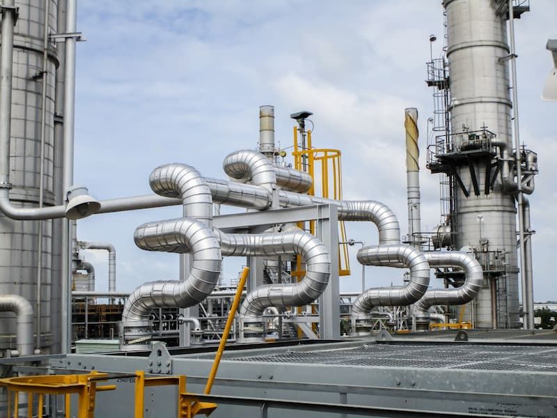
Insulated process piping and columns in an industrial treatment facility
Capture and regeneration systems require coordinated insulation around columns, piping, supports, access platforms and process interfaces.
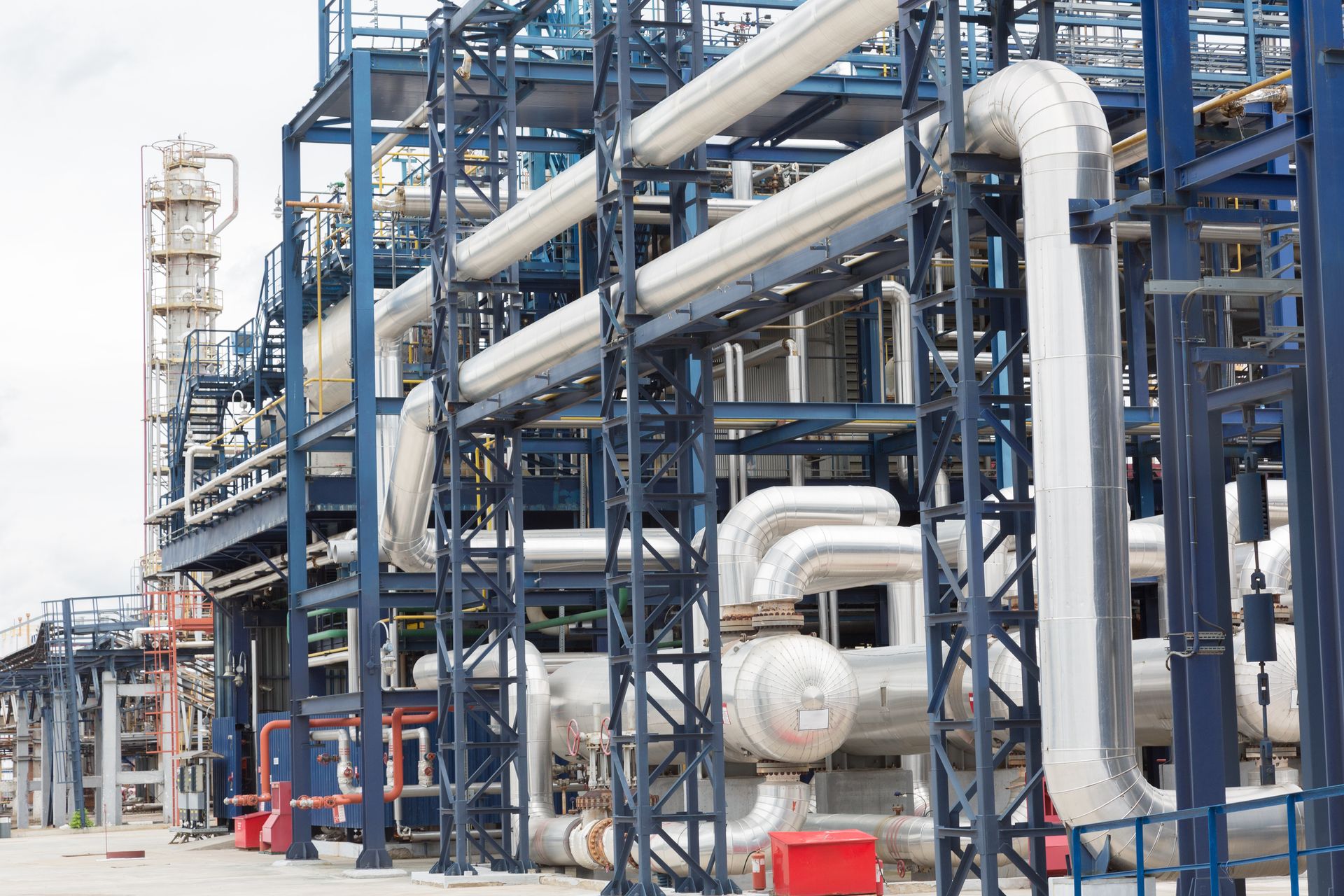
Insulated process piping and vessels at a compression and conditioning facility
Compression and conditioning areas combine hot discharge duty, cooling, separation, dehydration, vibration and maintenance access.
Compression and dehydration

CO₂ Compression, Intercooling and Dehydration Insulation

Compression trains create several distinct insulation duties: hot compressor-discharge piping, interstage systems, intercoolers and aftercoolers, knockout drums, separators, dehydration units, regeneration equipment and high-pressure export piping.

Thermal requirements may also intersect with vibration, noise, inspection frequency and rapid component access. Removable insulation jackets can be engineered for selected valves, flanges, strainers and equipment items without treating them as generic one-size-fits-all covers.

01
Temperature and Operating CasesNormal operation, turndown, start-up, shutdown, standby and depressurisation inputs.
02
Thermal and Acoustic ObjectivesHeat conservation, accessible surface temperature, condensation, noise and equipment constraints.
03
Supports, Movement and VibrationShoes, rings, penetrations, cladding attachments and interfaces assessed for the actual equipment.
04
Maintainable ClosureRemovable or sectional details, identification, reinstallation control and inspection access.
For maintenance-critical components, continue to Removable Insulation Jackets.
Refrigerated liquid CO₂

Low-Temperature Insulation for Liquid-CO₂ Storage and Export Systems

CO₂ liquefaction units, refrigeration equipment, buffer and storage tanks, loading lines, pumps, valves, manifolds and ship-loading connections require a low-temperature system that limits heat ingress and controls condensation and vapour ingress.

Depending on the approved design conditions, potential system directions may include cellular glass, PIR/PUR, flexible aerogel-based products, suitable elastomeric systems, multi-layer cold-insulation assemblies, low-permeance vapour retarders, protective cladding and load-bearing insulation inserts.
  • Heat-gain and external-surface condensation assessment
  • Continuous vapour-retarder design at joints and penetrations
  • Low-temperature pipe supports and thermal-bridge control
  • Contraction, movement and sealed termination details
  • Tank, loading-arm, pump, valve and manifold interfaces
Terminology: refrigerated liquid CO₂ service should generally be described as low-temperature or refrigerated liquid-CO₂ duty. It should not automatically be labelled “cryogenic CO₂” without a project-specific temperature basis.
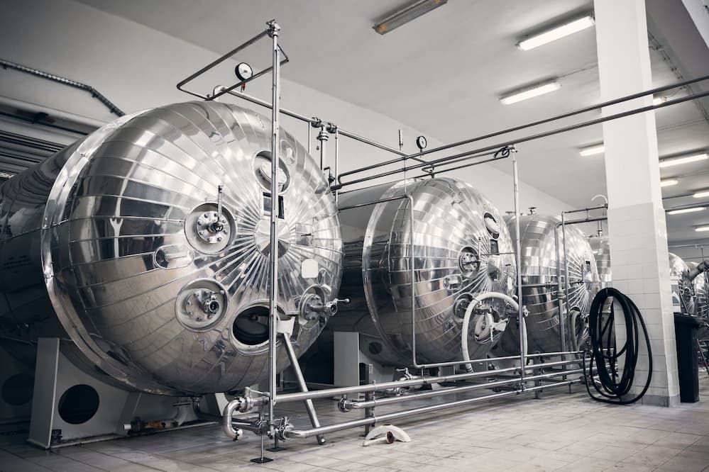
Metal-jacketed insulated horizontal process storage vessels
Low-temperature storage and transfer systems depend on vapour-control continuity, supports, penetrations and maintainable terminations.
CO₂ transport and flow assurance

Thermal and Insulation Design for Dense-Phase CO₂ Pipelines

Pipeline insulation must be justified by hydraulic, flow-assurance, integrity and transient analyses—not copied from conventional oil and gas service.

Fluid basis

Composition and Water Content

CO₂ purity, moisture and impurities influence corrosion risk, phase behaviour and the pressure–temperature envelope used by the process team.

Operating envelope

Phase Stability

Ambient heat transfer, pressure drop and operating cases are reviewed against the approved flow-assurance model and phase-boundary criteria.

Installation

Aboveground, Buried or Offshore

Air, soil or seawater temperature, solar exposure, wind, burial conditions, coatings and external protection affect the thermal design.

Transient cases

Start-Up and Shutdown

Warm-up, cool-down, stagnant conditions, restart, turndown and pressure changes can govern the required thermal response.

Integrity

Supports, Movement and CUI

Thermal expansion, shoes, anchors, field joints, water shedding, coating and inspection access are coordinated with any external insulation.

Design decision

Insulate Only When Justified

Some dense-phase CO₂ pipelines may not require external insulation. Unnecessary insulation can add cost, complexity and CUI exposure.

Important: ERATHERM’s insulation design must use the approved process, pipeline, materials and flow-assurance basis. Insulation does not replace hydraulic analysis, pressure-integrity design or CO₂ composition control.
Abnormal and transient conditions

Depressurisation, Dry-Ice Formation and Minimum Metal Temperature

Rapid pressure reduction can create severe local cooling. This condition is assessed with process safety, flow-assurance, piping and materials engineering—not by insulation selection alone.

Engineering IssueWhy It MattersInsulation InterfaceRequired Coordination
Rapid Decompression CoolingTemperature can fall sharply during blowdown, relief or loss of pressure.Evaluate layer temperatures, contraction, local exposure and system behaviour during the defined event.Process safety, dynamic simulation, piping and materials teams.
Dry-Ice FormationSolid CO₂ may form in relevant pressure–temperature conditions and affect flow or equipment operation.Do not claim that added insulation eliminates the risk; use approved depressurisation analysis.Process, flow assurance, operations and relief-system design.
Minimum Metal TemperatureLow local metal temperature can challenge material toughness and design limits.Thermal response may be one input, but metallurgy and code compliance govern acceptance.Materials, mechanical integrity and equipment/piping code owners.
Valves and RestrictionsPressure-drop locations can create local low-temperature zones and thermal cycling.Use project-specific removable, vapour-controlled or protective details where approved.Process, valve vendor, piping and maintenance teams.
Personnel ExposureCold surfaces, venting and CO₂ release can create contact and atmospheric hazards.Surface protection is only one control within the facility’s complete HSE strategy.HSE, process safety, ventilation and operations teams.

Final acceptance criteria, event duration and design temperatures must come from the approved project safety and process basis.

Moisture and integrity control

Condensation, Vapour Ingress and CUI Control in CCUS Facilities

A robust system coordinates the substrate coating, insulation, vapour retarder where required, cladding, sealants, fasteners, supports, penetrations, drainage and inspection strategy. No single insulation material can guarantee CUI prevention.

01
Substrate and Coating ReleaseSurface condition, approved coating, temperature compatibility and inspection hold point.
02
Thermal and Vapour-Control AssemblyMaterial, thickness, layers, joint treatment and continuous vapour control for the defined duty.
03
Weather Envelope and DrainageCladding, overlaps, flashings, penetrations, terminations, water shedding and low-point details.
04
Inspection and Repair AccessRemovable zones, inspection ports, sectional closures, tagging and damage-response procedures.
System principle: long-term performance depends on joints, cladding, drainage, supports, penetrations and inspection access—not insulation material alone.
Integrated delivery

ERATHERM CCUS Insulation Engineering Workflow

The scope can be delivered as consultancy, detail engineering, supply, installation, QA/QC or an integrated package.

STEP 01Inputs & CasesProcess data, pressure–temperature envelope, drawings, specifications and operating scenarios.
STEP 02Thermal AnalysisHeat flow, condensation, surface temperature, low-temperature and transient criteria.
STEP 03System SelectionMaterials, layers, vapour control, cladding, supports and inspection philosophy.
STEP 04Detail EngineeringSystem matrix, drawings, BOM/MTO, specifications, method statements and ITP.
STEP 05Supply & InstallationApproved submittals, procurement, prefabrication, qualified execution and inspections.
STEP 06Turnover & SupportPunch close-out, records, as-built documents and maintenance recommendations.
Engineering deliverables

Complete CCUS Insulation Engineering Package

Design Basis ReviewOperating, transient and environmental inputs
Thermal Calculation ReportHeat loss/gain, surface temperature and condensation
System Selection MatrixHot, cold, refrigerated and cycling duties
Insulation Class MatrixLine, equipment and service classification
Detail DrawingsSupports, penetrations, equipment and removable zones
BOM / MTOTraceable project quantities and material schedules
Technical SpecificationMaterials, workmanship and acceptance criteria
Method Statement & ITPExecution sequence, inspections and hold points
CUI and Moisture ReviewCoating, drainage, cladding and inspection interfaces
Site and QA/QC SupportInstallation control, punch and turnover dossier
Technical framework

Standards and Project References

Applicable editions and contractual precedence must be confirmed for each project.

ISO 12241:2022Thermal-insulation calculations for building equipment and industrial installations.
ASTM C680Computer calculation of heat loss/gain and surface temperatures for insulated systems.
ISO 27913:2024CO₂ pipeline transportation systems; supports the pipeline engineering interface rather than serving as an insulation-thickness standard.
DNV-RP-F104Design and operation of carbon-dioxide pipelines; relevant to integrity and operating-envelope coordination.
CO₂ transportation references do not replace the project’s approved thermal calculation method, process simulation, materials selection or contractual insulation specification.
Industrial delivery capability

Established Insulation Expertise for Emerging CCUS Infrastructure

ERATHERM brings industrial thermal, cold and cryogenic insulation experience to CCUS projects through engineering, material selection, detail design, application and QA/QC. The final system is developed around approved project data—not generic sustainability claims.

20+ YearsIndustrial insulation and field delivery experience
1,000,000+ m²Completed insulation applications
15,000+ MWExperience across major energy projects
3 ContinentsEngineering and project execution capability
Frequently asked questions

CCUS and Carbon Capture Facility Insulation FAQ

Why is insulation required in a carbon capture facility?
Insulation may be required to control heat loss or heat gain, maintain process temperature, reduce regeneration energy demand, protect personnel, prevent external condensation, limit vapour ingress and support process stability. The need and thickness must be determined for each equipment item and operating case.
Which CCUS equipment normally requires thermal insulation?
Potential scopes include flue-gas ducts, stripper and regeneration systems, reboilers, solvent piping, steam and condensate lines, compressor discharge and interstage piping, separators, dehydration equipment, refrigerated liquid-CO₂ systems, tanks, loading lines, valves, flanges and selected transport or injection facilities. Not every item is automatically insulated.
Does every dense-phase CO₂ pipeline require insulation?
No. The requirement depends on stream composition, pressure–temperature conditions, ambient or soil/seawater exposure, hydraulic and flow-assurance analysis, start-up, shutdown and depressurisation cases, and the integrity strategy. Unnecessary insulation may increase cost and CUI exposure.
How does CO₂ composition affect insulation-system design?
CO₂ purity, water content and impurities influence phase behaviour, corrosion risk and the approved operating envelope. Insulation design uses these process and flow-assurance outputs; it does not independently define acceptable CO₂ composition.
How is liquid-CO₂ piping insulated?
A project-specific low-temperature system may combine cellular glass, PIR/PUR, flexible aerogel-based or other approved insulation with continuous vapour control, sealed penetrations, suitable cladding, load-bearing support inserts and contraction details. Final materials and thickness follow the design temperature, heat-gain and condensation criteria.
Is liquid CO₂ considered a cryogenic service?
Not automatically. Refrigerated liquid CO₂ is generally better described as low-temperature or refrigerated liquid-CO₂ service. Whether a project classifies a particular condition as cryogenic depends on its temperature basis, specification and applicable engineering definitions.
How are condensation and CUI controlled in CCUS facilities?
Control requires a complete system: suitable substrate coating, insulation and vapour-retarder design, sealed joints and penetrations, weatherproof cladding, drainage, water shedding, thermal-bridge treatment, damage repair and planned inspection access. No insulation material alone prevents CUI.
What happens during CO₂ pipeline depressurisation?
Rapid pressure reduction can cause strong cooling and, under relevant conditions, possible dry-ice formation. Minimum metal temperature, local restrictions, event duration and material suitability must be assessed by process safety, flow-assurance, piping and materials teams. Insulation is only one interface in that analysis.
Can ERATHERM provide complete insulation detail engineering and installation?
Yes. ERATHERM can provide design-basis review, thermal calculations, material and system selection, insulation class matrices, detail drawings, support and vapour-control details, BOM/MTO, specifications, method statements, ITP, supply, installation, QA/QC and site supervision according to the agreed project scope.

Develop Your CCUS Facility Insulation Scope

Share the process data, pressure–temperature cases, equipment and line lists, drawings, specifications and project objectives. ERATHERM can structure the engineering, supply, application and QA/QC package around the facility’s actual operating envelope.

Final insulation materials, thicknesses, layer sequence, vapour-control strategy, coating, cladding, support details, transient criteria, surface-temperature targets, fire or acoustic requirements, inspection plan, quality controls and applicable standards are project-specific. They must be confirmed against the contract, approved process and flow-assurance basis, equipment and piping data, drawings, manufacturer information, HSE requirements, environmental exposure and maintenance programme. References on this page provide an engineering framework and do not imply that every standard applies to every project.