
Eratherm İzolasyon A.Ş.
Thermal engineering · Onshore · Offshore · Process pipelines

Oil and Gas Pipeline Insulation Engineering

ERATHERM designs and delivers industrial pipeline insulation systems that preserve process temperature, control heat loss or gain, coordinate with heat tracing, manage condensation and weather exposure, and reduce corrosion-under-insulation risk across oil, gas, refinery, petrochemical and terminal facilities.

Heat-loss and surface-temperature calculations Hot, cold and traced pipeline systems Engineering · Supply · Installation · QA/QC
Process ControlTemperature retention, viscosity control, freeze protection and condensation management
System EngineeringInsulation, tracing, supports, vapour control, cladding and interfaces designed together
CUI-Aware DesignWater shedding, drainage, coating coordination and inspection access
Turnkey DeliverySurvey · Calculation · Materials · Application · Inspection · Turnover
Beyond insulation thickness

What Pipeline Insulation Must Control

Oil and gas pipeline insulation is a complete thermal and weather-protection system built around the transported fluid, operating envelope, route and maintenance philosophy. The required outcome may be heat conservation, heat-gain limitation, personnel protection, viscosity control, hydrate or wax-risk management, condensation prevention, freeze protection or stable operation of a heat-traced line.

The design must extend beyond straight pipe. Valves, flanges, fittings, branch connections, pipe shoes, supports, expansion joints, instruments, drains and insulation terminations can create thermal bridges, moisture entry points and local discontinuities. These details often determine field reliability more than the nominal insulation material alone.

ERATHERM integrates thermal calculations, material selection, vapour control, mechanical protection, support details, CUI strategy, constructability and inspection requirements into one project-specific system.
Core principle: A pipeline insulation system is successful only when its calculated performance survives supports, penetrations, weather, maintenance and real installation tolerances.
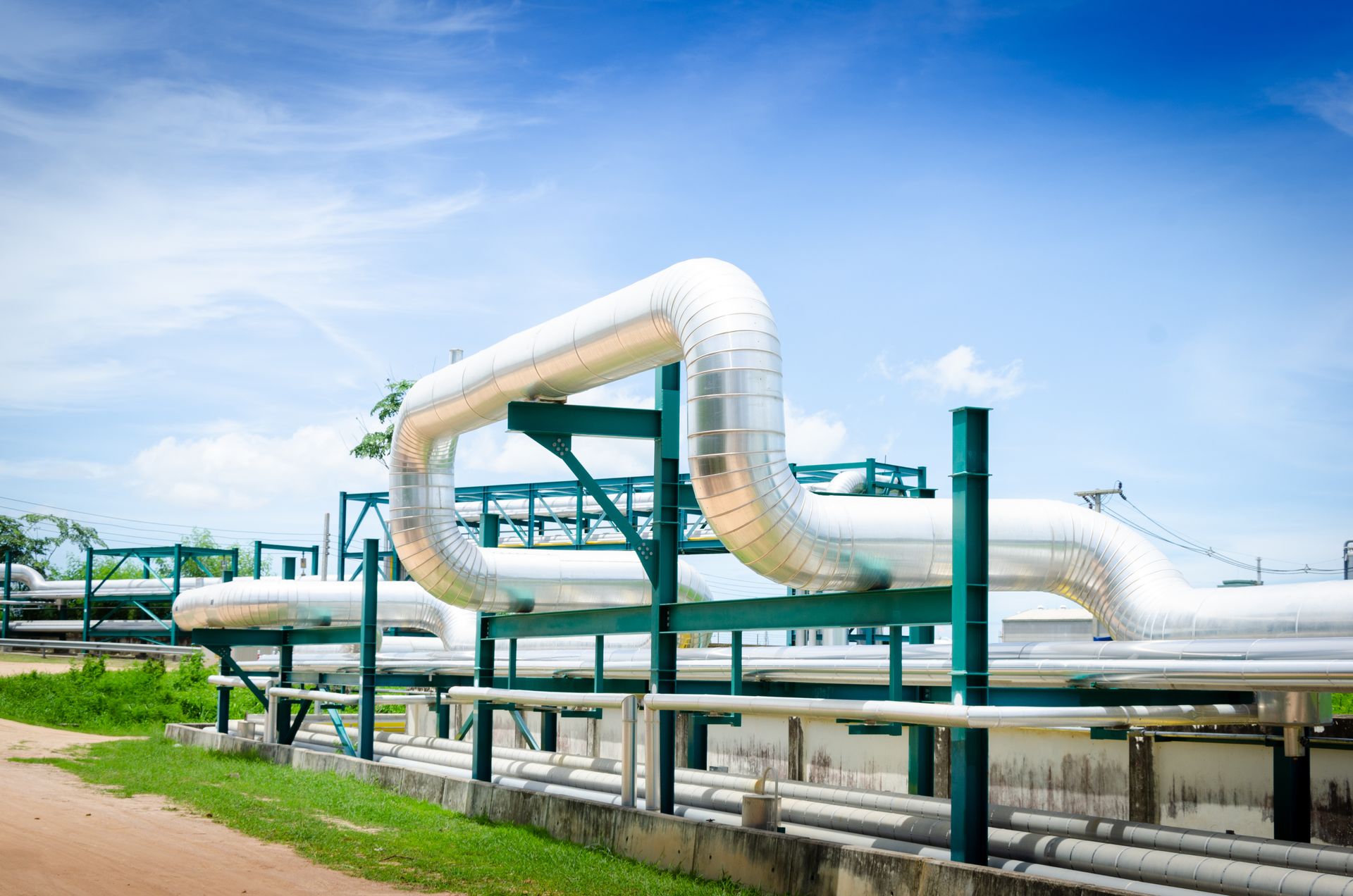
Insulated oil and gas process pipelines installed in an outdoor industrial facility
Outdoor pipeline systems require thermal continuity, water-shedding geometry, movement allowance and durable mechanical protection
Project environments

Pipeline Insulation Across the Oil and Gas Value Chain

The same material schedule should not be copied across every facility. Exposure, operating modes, accessibility and consequence of failure change the insulation architecture.

01

Refineries & Petrochemical Plants

Dense process piping, cycling services, steam and hot-oil lines, high-maintenance fittings, CUI exposure and shutdown-driven replacement scopes.

02

Onshore Oil & Gas Facilities

Gathering, treatment, compression, metering, storage and transfer systems exposed to wind, rain, solar load, dust and wide ambient variation.

03

Offshore & Marine Assets

Restricted space, salt-laden atmosphere, wind, washdown, vibration, fire philosophy, weight control and demanding inspection access.

04

Terminals & Storage Facilities

Loading and unloading lines, tank connections, manifolds, pump stations and intermittent operating modes requiring controlled preservation.

Service-specific architecture

Hot, Cold and Heat-Traced Pipeline Insulation Systems

The fluid condition, minimum and maximum temperatures, operating cycle and shutdown case define the system—not a generic hot-versus-cold label.

Hot service

Heat Conservation & Personnel Protection

Systems for hot oil, steam, condensate, process gas and heated hydrocarbons, designed around heat-loss limits, surface-temperature objectives, thermal movement and cladding durability.

Cold service

Heat-Gain & Condensation Control

Closed-cell or otherwise suitable systems with continuous vapour-control architecture, sealed joints and engineered penetrations for condensation-sensitive service.

Traced lines

Heat Tracing Coordination

Insulation thickness, pipe temperature, tracer type, control logic, sensor position, heat-transfer path and worst-case ambient conditions evaluated as one operating system.

Cyclic operation

Start-Up, Shutdown & Standby Cases

Normal duty alone is insufficient where lines cycle, remain stagnant, cool during shutdown or require controlled warm-up and preservation.

Temperature-sensitive fluids

Viscosity, Wax, Hydrate & Freeze Risk

Thermal design aligned with process-engineering limits and operating procedures, without treating insulation as a substitute for required process safeguards.

Special exposure

Fire, Acoustic & Mechanical Objectives

Thermal insulation coordinated with separately defined fire-protection, acoustic, impact, vibration or chemical-resistance requirements where the project demands them.
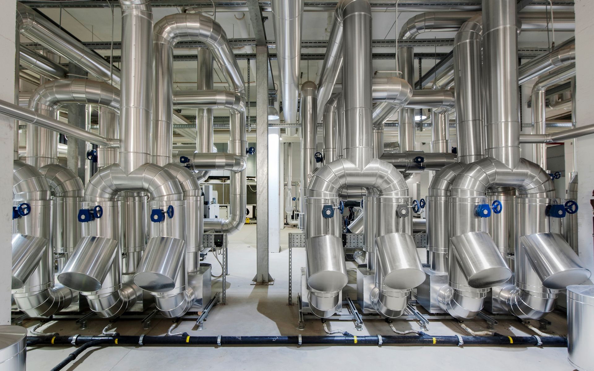
Metal-jacketed process piping showing elbows, branches and valves
Elbows, branches, valves, instruments and terminations must retain the same thermal and weatherproofing logic as straight pipe
Complete insulation envelope

Pipeline Insulation System Architecture

Final materials and layer sequence are selected from approved temperatures, design thermal conductivity, chemical exposure, fire philosophy, geometry, available clearance, inspection plan and project specifications.

01
Pipe Surface & CUI CoatingSurface preparation and coating system coordinated with substrate, service temperature, cycling, insulation chemistry and the facility CUI programme.
02
Heat Tracing and Instrument InterfacesTracer layout, heat-transfer aids, sensors, junctions and access points positioned before insulation closure where applicable.
03
Thermal Insulation LayersMaterial, thickness, number of layers, joint staggering, orientation and expansion details selected for the complete service envelope.
04
Vapour Control or Separation LayersContinuous vapour barrier, retarders, foils, membranes or separators used only where the service and material system require them.
05
Jacketing & WeatherproofingMetallic or approved non-metallic protection with controlled seams, overlaps, closures, flashings, drainage and movement allowance.
06
Supports, Terminations & Inspection PointsPipe shoes, support blocks, end caps, removable covers, inspection plugs and adjacent-system interfaces detailed as part of the envelope.
Calculation and detail design basis

Engineering Inputs That Define the Pipeline System

Reliable insulation begins with complete process, mechanical, environmental and operating data. Missing inputs are identified as assumptions and closed before final design.

Process

Fluid & Operating Envelope

Fluid composition, normal/design temperatures, pressure, flow regime, allowable heat loss or gain, minimum maintain temperature and upset conditions.

Ambient

Environmental Design Cases

Air temperature, wind, solar exposure, humidity, rain, marine atmosphere, washdown, fire exposure and operating location.

Geometry

Line, Fittings & Clearances

Pipe size, routing, fittings, valves, flanges, supports, instruments, spacing, access, cladding diameter and clash constraints.

Operation

Transient & Standby Modes

Start-up, shutdown, no-flow, blocked-in, intermittent duty, drain-down, preservation, emergency and restart scenarios.

Tracing

Heating System Integration

Electric or fluid tracing duty, tracer location, control philosophy, sensor arrangement, power availability and failure cases.

Integrity

CUI & Maintenance Strategy

Coating, water-entry risk, inspection intervals, removable locations, drainage, access, expected service life and repair philosophy.

Interfaces govern performance

Heat Tracing, Pipe Supports and Thermal Bridges

A heat-traced line should be checked as a combined pipe–tracer–insulation–control system. Tracer output alone does not establish the maintained fluid temperature. Pipe diameter, fluid state, ambient case, insulation performance, contact arrangement, control set points and local heat losses all influence the result.

Pipe shoes, guides, anchors, supports and penetrations bypass the ideal cylindrical insulation layer. They may increase heat loss, create cold spots or condensation, interfere with vapour continuity, concentrate movement and provide paths for water entry. Support insulation and thermal blocks must also satisfy compressive load, creep, temperature and moisture requirements.
  • Heat-loss and heat-gain calculation for defined design cases
  • Tracer duty and insulation thickness coordination
  • Multi-layer joints and expansion arrangement
  • Pipe shoe, anchor and support-block detailing
  • Termination, sensor and junction-box access
  • Local thermal-bridge review and constructability check
Design boundary: Insulation engineering supports the process-temperature objective; final heat-tracing design and protection philosophy must be coordinated with the responsible process, piping, electrical and control disciplines.
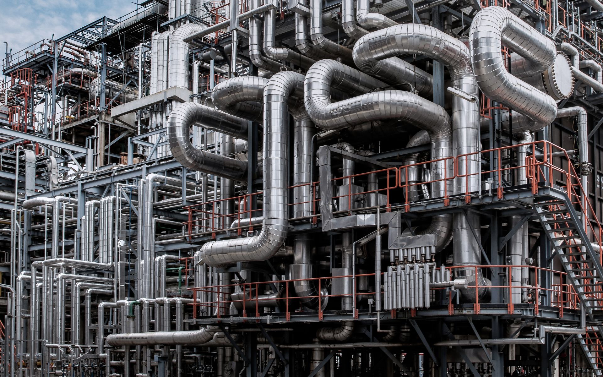
Complex insulated piping network in an oil and gas processing facility
Complex routes require coordinated insulation thickness, support geometry, movement, access and cladding fabrication
Insulated refinery and petrochemical pipelines with weatherproof metal cladding
CUI control depends on coating, insulation, cladding details, water management, inspection and disciplined repair—not one component alone
Asset integrity beneath insulation

Corrosion Under Insulation: A Systems Approach

Insulation does not create corrosion by itself, and no insulation material can guarantee CUI prevention. Risk develops through the interaction of substrate, coating, temperature, cycling, contaminants, insulation chemistry, water ingress, retention, geometry, weatherproofing quality, maintenance damage and inspection strategy.

Pipeline details should shed water away from seams and penetrations, avoid moisture traps, allow movement without tearing the outer cover and provide controlled access where the inspection plan requires it. Coating selection remains a corrosion-engineering decision and must be compatible with the actual temperature range and project requirements.

  • Project CUI risk review and service categorisation
  • Substrate preparation and coating coordination
  • Jacketing seam, overlap, flashing and drainage details
  • High-risk penetrations, terminations and support interfaces
  • Removable covers and planned inspection access
  • Repair details, close-out records and quality surveillance
CUI principle: The insulation system must be designed for the facility’s inspection and maintenance programme; closing the cladding is not the end of asset-integrity management.
Material-neutral engineering

Pipeline Insulation Material Selection by Service Duty

Materials are shortlisted against the approved design basis. The matrix illustrates decision logic and does not replace project-specific selection or manufacturer data.

Service conditionPrimary design concernPotential material familiesCritical verification
General hot process pipingHeat conservation, surface temperature, movement and weather resistanceMineral wool, calcium silicate, cellular glass, aerogel or other approved high-temperature systemsDesign conductivity, temperature limit, jointing, compression, cladding and cyclic behaviour
High-temperature or space-constrained dutyThickness, thermal cycling, limited clearance and rapid installationAerogel, microporous insulation, selected fibrous or rigid high-temperature systemsHot-face limit, design conductivity, handling, mechanical protection and economics
Cold and condensation-sensitive serviceHeat gain, vapour ingress, condensation and iceCellular glass, PIR/PUR, elastomeric or other approved closed-cell systemsVapour permeability, joint sealing, dimensional stability, fire/chemical compatibility and inspection philosophy
Dual-temperature or cyclic serviceExpansion/contraction, moisture accumulation and changing dew-point conditionsProject-specific hybrid or multi-layer systems selected from validated temperature rangesFull cycle analysis, interfaces, vapour strategy, movement and long-term durability
Offshore and marine exposureSalt, wind, washdown, weight, vibration, fire philosophy and restricted accessProject-approved thermal core with corrosion-resistant cladding and robust attachment systemEnvironmental compatibility, seams, fasteners, drainage, fire requirements and maintenance access
Buried or submerged insulated pipelineSoil/water exposure, external pressure, water tightness, coating and field jointsSpecialist factory-applied or project-qualified insulated pipeline systemsPipeline system qualification, coating interfaces, field joints, hydrostatic/mechanical loads and installation method

Buried, subsea and factory-pre-insulated pipelines are separate engineered products and are not represented by a standard above-ground insulation detail. Their pipeline, coating, joint and installation standards must govern the complete system.

Installation quality protects the design

Pipeline Insulation Installation and QA/QC

Calculated performance is converted into field reliability through controlled storage, substrate release, layer installation, joint staggering, vapour sealing, support details, cladding fabrication and final weatherproofing. Inspection points are planned before work begins and linked to the approved specification, method statement and ITP.

01

Before Closure

Material identity, storage, surface condition, coating release, tracing, insulation thickness, layer sequence, joints and support interfaces.

02

Weather Envelope

Vapour-control continuity, cladding alloy and thickness, seam orientation, overlaps, fastening, penetrations, flashings and drainage.

03

Turnover

Inspection records, punch close-out, repair traceability, line and area release, as-built changes, quality dossier and maintenance notes.

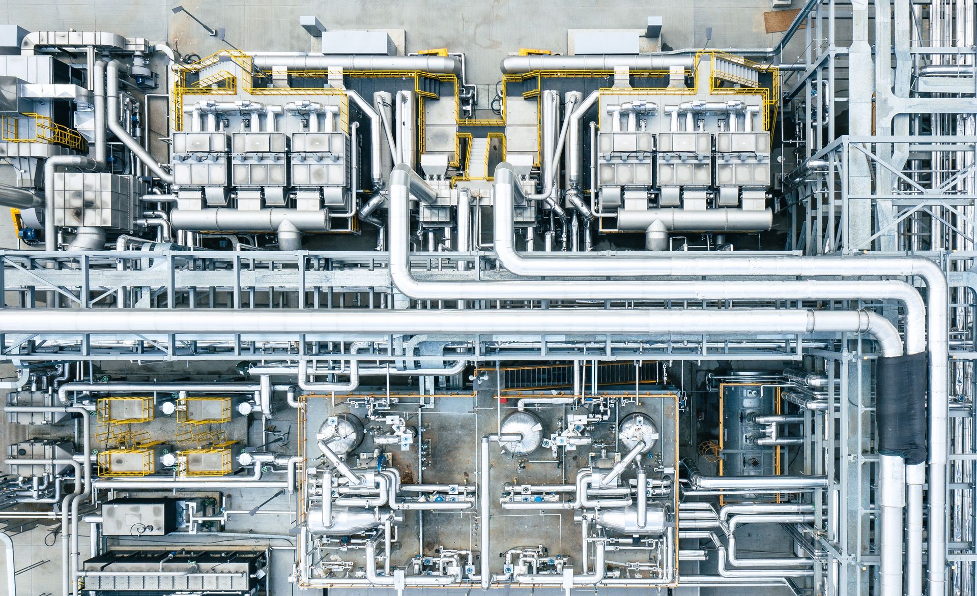
Large oil and gas processing facility with insulated pipelines
ERATHERM combines insulation engineering with field application, supervision, inspection and turnover documentation
From process data to field turnover

ERATHERM Pipeline Insulation Delivery Workflow

The scope can cover one critical line, a brownfield CUI campaign, a shutdown package or a complete new-build facility.

STEP 01Data & Site ReviewLine list, P&IDs, isometrics, temperatures, ambient cases, tracing, specifications and field constraints.
STEP 02Thermal DesignHeat loss or gain, surface temperature, dew point, tracing coordination and thickness optimisation.
STEP 03System EngineeringMaterial matrix, layer sequence, supports, vapour control, cladding, CUI and inspection details.
STEP 04Planning & SupplyMTO, procurement mapping, work packs, logistics, storage controls and installation sequence.
STEP 05Field ExecutionSurface release, insulation, vapour sealing, cladding, special details, supervision and safe access.
STEP 06QA/QC & TurnoverITP records, punch closure, as-built status, dossier, maintenance guidance and final handover.
Construction-ready outputs

Pipeline Insulation Engineering Deliverables

Design BasisRequirements, operating cases, assumptions, criteria and discipline interfaces
Thermal Calculation ReportHeat loss/gain, surface temperature, dew point and thickness assessment
Material Selection MatrixService-based insulation, vapour-control, jacketing and accessory selection
Insulation ScheduleLine, diameter, service, material, thickness, layers and system code
Project DetailsSupports, shoes, elbows, branches, valves, flanges, terminations and penetrations
Heat-Tracing InterfacesThermal coordination inputs, sensor access and insulation close-out details
MTO & Work PacksQuantities, fabrication requirements, line packages and execution sequencing
Specification, Method & ITPMaterials, workmanship, inspection criteria, records and acceptance controls
Inspection RecordsMIR/WIR support, hold-point records, punch status and repair traceability
Turnover DossierApproved documents, as-built changes, certificates and close-out records
Applicable technical framework

Standards Are Selected by Project Scope

Contract requirements, approved process data and project specifications govern. Standards below are applied only where relevant to the defined service.

ISO 12241:2022Calculation rules for heat-transfer-related properties of industrial insulation systems.
ASTM C680Heat gain/loss and surface-temperature estimation for insulated systems.
ISO 15758:2014Water-vapour diffusion calculation for cold-pipe insulation systems where applicable.
AMPP SP0198Systems approach to controlling corrosion under thermal insulation and fireproofing materials.
NORSOK M-004 / CINI ManualPiping and equipment insulation frameworks when contractually specified for the project.
Project Material and Jacketing StandardsApplicable ASTM, EN, ISO, owner, EPC, offshore and manufacturer requirements for insulation, cladding and accessories.
Industrial field experience

Engineering Built for Critical Facilities

ERATHERM combines design, material engineering, procurement, field execution and quality control across refinery, petrochemical, energy, process and heavy-industry projects. Pipeline insulation scopes can be delivered for new construction, brownfield improvement, CUI mitigation, planned shutdowns and operating-facility maintenance.

1,000,000+ m²Completed industrial insulation
15,000+ MWPower-plant project experience
20+ YearsThermal engineering and field expertise
3 ContinentsInternational critical-facility and EPC experience
Frequently asked questions

Oil and Gas Pipeline Insulation FAQ

Why are oil and gas pipelines insulated?
Pipelines are insulated to control heat loss or gain, preserve process temperature, manage viscosity, support freeze or condensation prevention, reduce accessible surface temperature and improve energy performance. The required objective depends on the fluid, operating mode, environment and process limits.
How is pipeline insulation thickness calculated?
Thickness is calculated from pipe size, fluid and pipe temperature, ambient temperature, wind, solar exposure where relevant, insulation design conductivity, surface emissivity, heat-loss or heat-gain target, surface-temperature objective, tracing duty, clearances and economic criteria. Approved project data must govern the final calculation.
Which insulation material is best for oil and gas piping?
There is no single best material for every pipeline. Mineral wool, calcium silicate, cellular glass, PIR/PUR, elastomeric insulation, aerogel and other systems each suit different temperatures, moisture conditions, mechanical loads, fire philosophies and project specifications. Selection must evaluate the full service envelope and complete system.
What is different about cold pipeline insulation?
Cold and condensation-sensitive lines require control of water-vapour ingress as well as heat gain. Vapour-control continuity, sealed joints, penetrations, support interfaces and cladding details are critical. A standard hot-service system should not be assumed suitable for cold or cryogenic duty.
How does insulation work with electric or steam heat tracing?
The pipe, tracer, insulation and control system must be evaluated together. Tracer type and output, contact arrangement, sensor location, control set point, pipe size, fluid state, insulation thickness and worst ambient condition all influence the maintained temperature. Insulation alone cannot compensate for an incorrectly designed tracing system.
Can pipeline insulation prevent corrosion under insulation?
No single insulation material guarantees CUI prevention. Risk depends on coating, temperature, contaminants, water ingress and retention, cycling, weatherproofing, penetrations, maintenance damage and inspection. A systems approach combines coating, insulation, jacketing details, drainage, access and a defined inspection programme.
What details are most vulnerable to water ingress?
Common risk locations include terminations, vertical penetrations, pipe shoes, supports, low points, instruments, branch connections, damaged seams, flashing transitions, removable covers and interfaces with other insulation systems. These locations need project-specific water-shedding, sealing and inspection details.
Does ERATHERM provide installation and QA/QC as well as engineering?
Yes. ERATHERM can provide thermal calculations, material selection, detailed insulation engineering, MTO, procurement support, installation, field supervision, ITP implementation, inspection, punch close-out and turnover documentation as an integrated or separately defined scope.
What information is required for a pipeline insulation proposal?
Useful inputs include the line list, P&IDs or isometrics, pipe sizes and lengths, fluid and operating temperatures, design and standby cases, allowable heat loss or gain, heat-tracing data, ambient conditions, location, insulation specification, cladding requirements, support details, quantities, schedule and site photographs for brownfield work.
Turn process requirements into a field-ready system

Develop Your Pipeline Insulation Scope with ERATHERM

Share line data, operating and ambient conditions, tracing information, project specifications, drawings and site constraints. ERATHERM can define the thermal basis, insulation architecture, details, quantities, installation plan and quality controls.

Final insulation materials, thicknesses, layer sequence, vapour-control strategy, coating, heat tracing, cladding, support details, surface-temperature targets, fire or acoustic performance, quality controls and applicable standards are project-specific. They must be confirmed against the contract, approved process data, piping design, environmental conditions, manufacturer information, HSE requirements and the intended inspection and maintenance programme. References on this page are a technical framework and do not imply that every standard applies to every project.