Eratherm İzolasyon A.Ş.
ASTM C680 · ISO 12241 · Thermal Modelling · Life-Cycle Cost

Insulation Thickness Calculation & Heat-Loss Analysis

Engineering-grade thickness optimisation for hot, cold and cryogenic systems—combining heat-loss or heat-gain modelling, surface-temperature verification, condensation control, freeze protection, thermal-bridge review and life-cycle cost analysis.

  • ASTM C680-23a
  • ISO 12241:2022
  • Hot · Cold · Cryogenic
  • Steady-State · Transient
  • 2D / 3D FEA
  • TR + EN Reports
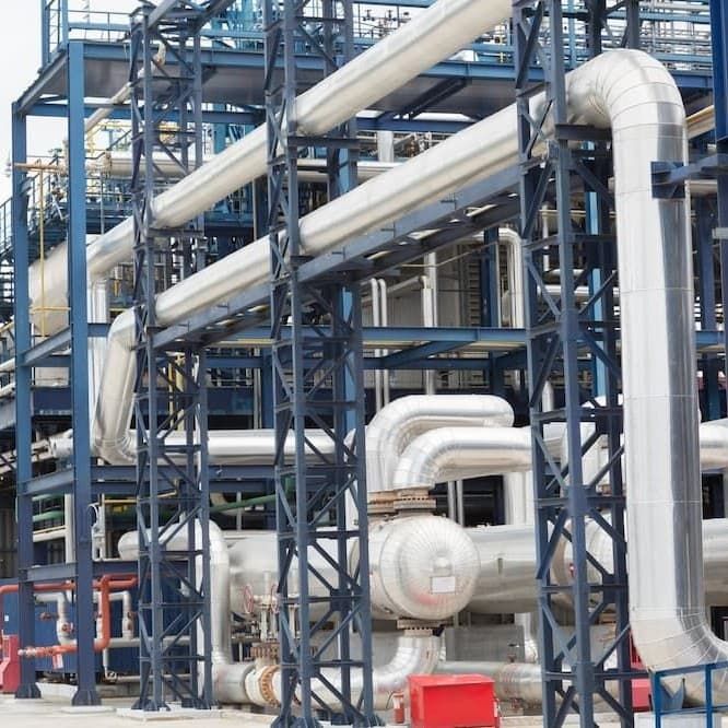
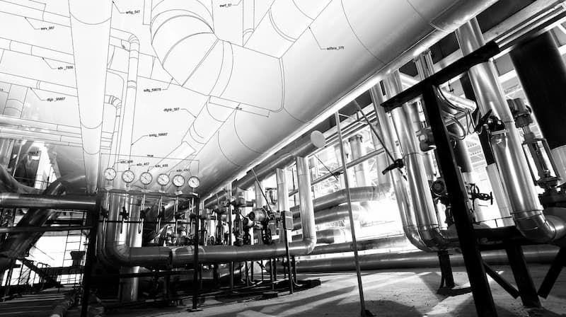
Industrial insulated piping used for insulation thickness and heat-loss analysis
One Model. Multiple Criteria. The governing thickness is selected only after every project-specific requirement is checked.
01 · MODEL Heat Loss / Gain & Surface Temperature
02 · VERIFY Condensation, Freeze & Personnel Protection
03 · OPTIMISE Material, Thickness, Energy & Carbon
04 · REPORT Audit-Ready Engineering Deliverables
Engineering Fundamentals

How Is Industrial Insulation Thickness Calculated?

Industrial insulation thickness is calculated by building a thermal-resistance model of the complete system—not by selecting a generic thickness from temperature alone. The model includes process temperature, geometry, pipe or equipment dimensions, ambient conditions, wind, radiation, cladding emissivity, each material layer and the temperature-dependent thermal conductivity λ(T) of the proposed insulation.

For pipes, vessels and tanks, geometry changes the resistance of every layer. The outer-surface temperature also changes convection and radiation, so it must be solved iteratively. ERATHERM evaluates multiple commercial thicknesses and checks each option against the governing design criteria before issuing a recommendation.

The technically minimum thickness and the economically optimum thickness are not always the same. A compliant result may control heat flow or surface temperature, while the life-cycle optimum may justify additional thickness through lower fuel, electricity, refrigeration and carbon costs.

One Thickness · Multiple Requirements

Which Criterion Governs the Final Thickness?

ERATHERM calculates every applicable criterion separately, identifies the controlling requirement and documents why the selected commercial thickness is technically and economically justified.

A thickness that controls energy loss may still fail condensation, personnel protection or process stability. The final recommendation must satisfy the complete design basis.

01

Heat Loss & Energy Conservation

Quantifies W/m, W/m², total kW and annual MWh loss from hot piping, equipment, turbines, furnaces, tanks and vessels. Alternative materials and thicknesses are compared on an identical basis.

Output · Heat loss + annual energy
02

Heat Gain & Refrigeration Load

Calculates heat ingress into chilled, refrigerated and cryogenic systems, including its effect on refrigeration demand, product temperature, cooldown duty and potential boil-off contribution.

Output · Heat gain + cooling load
03

Personnel-Protection Surface Temperature

Verifies the calculated outer-surface temperature against project criteria. Allowable contact conditions depend on jacketing material, contact duration and the accepted injury threshold—not one universal temperature limit.

Output · Surface-temperature compliance
04

Condensation & Dew-Point Control

Compares surface temperature with the calculated dew point and design margin. The assessment also reviews vapour-retarder continuity and long-term moisture ingress in cold insulation systems.

Output · Dew-point safety margin
05

Freeze Protection & Holdover Time

Uses transient energy balance for stagnant or low-flow lines, combining fluid inventory, initial temperature, ambient exposure, insulation and heat tracing to calculate the time to a critical temperature or freezing.

Output · Time to critical temperature
06

Economic Thickness & Life-Cycle Cost

Balances insulation CAPEX against discounted energy OPEX, maintenance, replacement allowance, fuel or electricity escalation, project life and optional carbon cost to determine the life-cycle optimum.

Output · LCC + NPV + payback

Asset-integrity overlay: Corrosion under insulation (CUI) is not treated as a simple thickness criterion. Water entry, coating condition, vapour barriers, operating cycles, material, jacketing details, inspection access and maintenance strategy are reviewed as a complete system.

Service-Specific Engineering

Hot, Cold, Cryogenic and Freeze-Protection Paths

The same thickness-selection rule cannot govern every service. Select a calculation path to see the dominant risks, engineering questions and typical outputs for that operating regime.

Hot Piping, Equipment, Turbines and Process Units

Hot-service calculations usually start with allowable heat loss, process-temperature retention, personnel protection or an economic objective. Radiation, jacketing emissivity and wind can have a decisive influence on the calculated outer-surface temperature.

  • Steam, condensate, thermal-oil and process piping
  • Boilers, reactors, furnaces, turbines and vessels
  • Heat loss in W/m, W/m², kW and annual MWh
  • Surface temperature and economic thickness
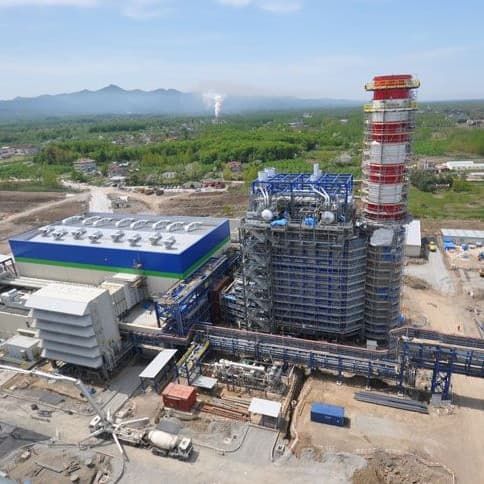
Industrial power plant for hot-service heat-loss and insulation optimisation
Heat-loss, process-control and life-cycle optimisation for energy-intensive assets.
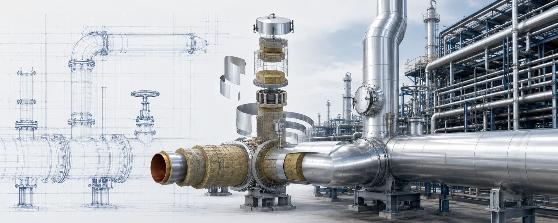
Industrial insulation system development from technical drawing to installed piping and equipment
From geometry and design data to a buildable, verifiable insulation system.
Calculation Methodology

From Standards-Based Calculation to Project-Specific Modelling

ERATHERM selects the simplest method that represents the physics accurately, then increases model fidelity where geometry, time dependency or external flow materially changes the result.

01 · 1D

ASTM C680 / ISO 12241 Calculation

Steady-state evaluation of flat, cylindrical and spherical systems with conduction, convection, radiation and iterative surface-temperature solution.

02 · 2D/3D

FEA for Thermal Bridges and Complex Geometry

Used for supports, nozzles, penetrations, tank skirts, anchors, valve bodies, discontinuities and local hot or cold spots that a one-dimensional model cannot resolve.

03 · TIME

Transient Thermal Analysis

Applied to startup, shutdown, cooldown, warm-up, holdover and time-to-freeze cases in which thermal mass and duration govern performance.

04 · FLOW

CFD-Coupled Heat-Transfer Assessment

Reserved for forced convection, complex external flow, ventilation, localized jets or flow–thermal interaction where a prescribed surface coefficient is inadequate.

When One-Dimensional Calculation Is Not Enough

Thermal Bridges, Transient Duty and Numerical Simulation

Standard calculations remain the primary method for regular geometry. Advanced numerical models are introduced only where they change design decisions, risk or the acceptance basis.

The deliverable states model boundaries, mesh or discretisation approach, material properties, boundary conditions, convergence criteria, assumptions and independent-check status.

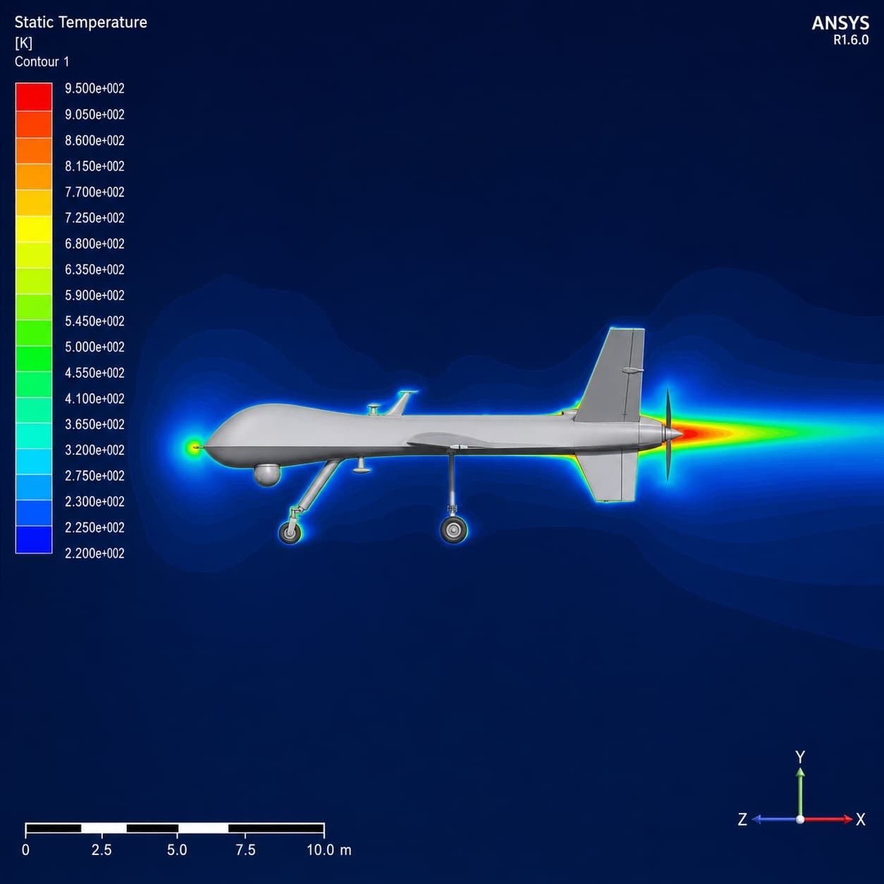
Representative numerical temperature-field simulation demonstrating advanced analysis capability
Physics Appropriate to the Question Representative numerical field visualisation. Project models are developed from the actual geometry and verified boundary conditions.
Thermal Bridge Model

Supports, Rings, Nozzles and Penetrations

Local metal paths may bypass the main insulation and dominate heat flow or surface temperature. ERATHERM models their real geometry and contact conditions instead of applying an arbitrary global correction.

  • Pipe shoes and support rings
  • Tank skirts, anchors and bottom details
  • Cladding connections and vapour-barrier discontinuities
Scenario Model

Startup, Shutdown and Abnormal Conditions

Normal operation may not be the controlling case. Transient analysis can compare cooldown, warm-up, emergency shutdown, loss of heat tracing and minimum-flow scenarios to identify the real design envelope.

  • Thermal mass and temperature history
  • Duration-dependent acceptance criteria
  • Sensitivity and uncertainty cases
Required Engineering Inputs

Reliable Results Begin with a Controlled Design Basis

A calculation is only as defensible as its inputs. ERATHERM issues an input and assumption register, identifies missing project data and documents conservative values that require client confirmation.

Engineering drawings coordinated with industrial insulation installation
01 · Process and Operating Data
Define the normal, minimum, maximum and design cases—not only one nominal temperature.
  • Process fluid or gas
  • Operating and design temperatures
  • Pressure and phase, where relevant
  • Flow, standby and shutdown modes
  • Allowable temperature change
  • Annual operating hours
02 · Geometry and Construction
Geometry determines thermal resistance and the correct reporting unit.
  • Pipe size, schedule and length
  • Tank, vessel or equipment dimensions
  • Flat, cylindrical or spherical surfaces
  • Existing wall and coating layers
  • Supports, nozzles and penetrations
  • Cladding type and surface condition
03 · Ambient and Exposure Conditions
Project climate data must represent the scenario being checked.
  • Indoor or outdoor installation
  • Ambient dry-bulb temperature
  • Relative humidity and dew point
  • Wind speed and orientation
  • Solar exposure and absorptivity
  • Elevation and surrounding conditions
04 · Insulation and Jacketing Candidates
Manufacturer data must match the proposed product, temperature range, density and ageing condition.
  • Candidate materials and densities
  • Approved λ(T) curves
  • Single or multilayer build-up
  • Contact resistance, if applicable
  • Jacketing material and emissivity
  • Vapour retarder and weather barrier
05 · Acceptance Criteria
Each criterion is stated in measurable engineering terms.
  • Maximum heat loss or heat gain
  • Target outer-surface temperature
  • Dew-point design margin
  • Allowable fluid temperature change
  • Required holdover time
  • Project or client specifications
06 · Economic and Carbon Assumptions
Transparent economic assumptions allow the result to be updated as energy prices or project terms change.
  • Fuel or electricity price
  • Boiler or refrigeration efficiency
  • Installed insulation cost
  • Project life and discount rate
  • Energy-price escalation
  • Emission factor and carbon price
Calculation Deliverables

Engineering Outputs That Can Be Reviewed and Built

ERATHERM reports the recommended commercial thickness together with the assumptions, governing criterion and performance results required by EPC, owner and independent third-party engineering review.

01 · THICKNESS

Recommended Commercial Build-Up

Layer-by-layer thickness, material, density, jacketing and relevant barrier requirements.

02 · THERMAL

Heat Flow and Surface Temperature

W/m, W/m², total kW, annual MWh, heat gain or loss and calculated outer-surface temperature.

03 · MOISTURE

Dew Point and Condensation Margin

Ambient dew point, calculated surface temperature, safety margin and vapour-control notes.

04 · TRANSIENT

Freeze or Holdover Time

Temperature history, time to critical condition and heat-tracing contribution where applicable.

05 · ECONOMIC

LCC, NPV and Payback

Insulation CAPEX, annual energy OPEX, simple payback, discounted cash flow and life-cycle optimum.

06 · CARBON

Energy and CO₂e Impact

Annual energy saving, fuel or electricity reduction and documented emission-factor basis.

07 · COMPARISON

Material–Thickness Matrix

Like-for-like technical and economic comparison of candidate materials and layer arrangements.

08 · ASSURANCE

Assumption and Compliance Register

Standards, data sources, exclusions, sensitivities, open points and independent-check record.

STEP 01Input & Assumption Register
STEP 02Thickness Iteration Matrix
STEP 03Verification & Sensitivity
STEP 04Checked Engineering Report
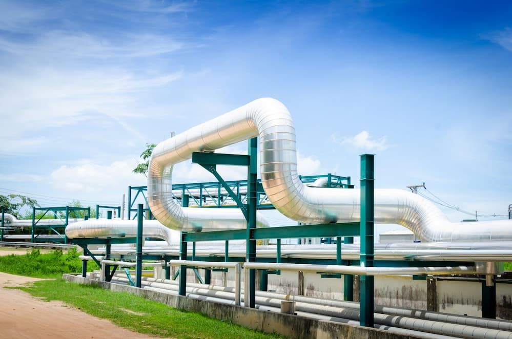
Industrial insulated piping representing material and thickness optimisation
Thickness is optimised with the complete material system—not conductivity alone.
Material and Thickness Optimisation

Compare Systems Using Real λ(T) Data

Thermal conductivity changes with mean temperature, density, ageing, moisture and product formulation. ERATHERM uses manufacturer-approved conductivity curves for the exact proposed product and compares realistic commercial build-ups rather than a single catalogue value.

Important: Vacuum + MLI performance depends on vacuum level, layer density, compression, seams, penetrations and residual-gas conduction. It is assessed as a system and is not inserted into a conventional material table using one generic λ value.

Explore the English insulation materials portfolio
Turkish materials portfolio (TR)

Hot Service

Mineral Wool & Glass Wool

Economical industrial systems assessed for service temperature, density, convection suppression, compression and jacketing.

Hot / Structural

Calcium Silicate

Rigid insulation considered where high service temperature, mechanical strength and durable geometry are required.

Cold / Cryogenic

Cellular Glass / Foamglas

Closed-cell systems evaluated for vapour resistance, dimensional stability, load-bearing details and tank-bottom applications.

Cold Service

PIR / PUR Systems

Prefabricated shells, blocks, in-situ injection or spray systems modelled with ageing, jointing and vapour-barrier requirements.

Space-Limited

Cryogel / Pyrogel Aerogel Blankets

Thin, flexible systems compared for constrained geometry, retrofit work, CUI management and demanding temperature ranges.

Extreme Temperature

Microporous & Ceramic Fibre

High-temperature or space-constrained systems assessed using product-specific data, shrinkage limits and installation design.

Double-Wall Systems

Expanded Perlite

Bulk-filled systems evaluated for annular geometry, packing condition, settlement allowance and vacuum or inert service.

Vacuum Service

Vacuum + MLI

Advanced cryogenic systems assessed using radiation, spacer, residual-gas, solid-conduction and installation-dependent performance.

View MLI engineering
Project-Specific

Hybrid Multilayer Systems

Combinations selected where thermal, vapour, fire, mechanical, acoustic or maintenance requirements cannot be met by one material.

Economic Insulation Thickness

Convert Thermal Performance into a Life-Cycle Decision

Economic thickness is the build-up that minimises total discounted cost over the selected project life while still satisfying every technical requirement. The analysis separates transparent assumptions from calculated results so future energy-price scenarios can be updated.

Installed CAPEXMaterial, accessories and installation
Annual Energy OPEXFuel, steam, electricity or refrigeration
EfficiencyBoiler, heater or refrigeration performance
Operating ProfileHours, load factor and scenarios
Discounted Cash FlowProject life, discount and escalation
Carbon ImpactCO₂e factor and optional carbon price
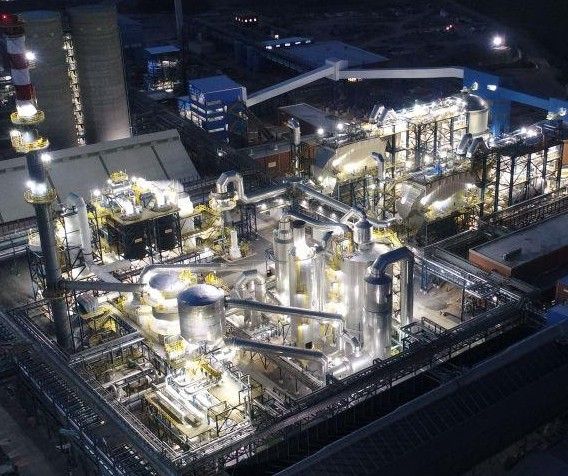
Large industrial facility evaluated for heat-loss, energy and carbon reduction
From W/m to Financial Impact Heat flow is translated into annual energy, cost, CO₂e, payback, NPV and life-cycle cost.
Standards and Technical Assurance

A Calculation Basis Matched to the Engineering Question

Standards are applied according to their actual scope. Project specifications, manufacturer data and documented engineering judgement are incorporated without presenting one standard as a substitute for the complete insulation-system design.

ASTM C680-23a Heat Flow and Surface Temperature

Primary calculation practice for insulated flat, cylindrical and spherical systems, including heat loss or gain and surface temperature.

ISO 12241:2022 Industrial Thermal-Insulation Calculation

Rules for industrial insulation heat-transfer calculations, predominantly steady-state, with simplified treatment of certain thermal bridges.

ASTM C1055 / ISO 13732-1 Contact and Personnel Protection

Supports evaluation of contact-burn risk using surface material, contact duration and accepted injury criteria rather than a universal limit.

ISO 15758 Water-Vapour Diffusion

Used where long-term vapour diffusion and condensation within cold pipe insulation must be assessed in addition to external surface dew point.

CINI Manual System and Installation Framework

Applied to material selection, system build-up, detailing and industrial installation requirements—not as the sole heat-transfer calculation method.

API RP 583 / AMPP SP0198 CUI Risk and System Integrity

Supports system-level review of coatings, water entry, materials, inspection, maintenance and corrosion-under-insulation control.

Project Specifications Client and EPC Requirements

Allowable heat flow, surface temperature, weather data, safety factors, material constraints and reporting format are incorporated into the design basis.

Manufacturer Data Product-Specific λ(T)

Conductivity curves, temperature limits, density, ageing, jointing and installation factors are verified for the actual proposed product.

Flat · Cylindrical · Spherical Single & Multilayer Steady-State Transient Thermal Bridges 2D / 3D FEA Life-Cycle Cost Independent Check
Frequently Asked Questions

Insulation Thickness Calculation FAQ

Concise answers to the questions most frequently raised by asset owners, EPC contractors, process engineers and insulation specialists.

Submit Your Calculation Case
How is industrial insulation thickness calculated?
A thermal-resistance model is built using process temperature, geometry, ambient conditions, convection, radiation, cladding emissivity and temperature-dependent insulation conductivity. Commercial thicknesses are iterated and checked against heat flow, surface temperature, condensation, process, freeze-protection and economic criteria as applicable.
Which standards are used for insulation thickness calculations?
ASTM C680 and ISO 12241 are the principal calculation references for regular industrial insulation geometries. ASTM C1055 and ISO 13732-1 may support personnel-protection assessment, ISO 15758 may be used for water-vapour diffusion, and project specifications determine client-specific criteria.
What is the difference between heat-loss and heat-gain calculations?
Heat-loss calculations quantify energy leaving a hot system; heat-gain calculations quantify energy entering a cold or cryogenic system. The governing criteria also differ: hot service often focuses on energy and touch protection, while cold service may be governed by condensation, refrigeration load or boil-off contribution.
How is economic insulation thickness determined?
Multiple commercial thicknesses are compared using installed CAPEX and discounted energy OPEX over the selected project life. The model can include maintenance, replacement, energy-price escalation, discount rate and carbon cost. The lowest compliant life-cycle cost identifies the economic optimum.
Is 60°C a universal safe-touch surface temperature?
No. Contact-burn risk depends on surface material, contact duration, user group and the accepted injury criterion. The project should define an appropriate personnel-protection requirement using relevant standards rather than assuming one universal surface-temperature limit.
How do you calculate insulation thickness to prevent condensation?
Ambient temperature and relative humidity are used to calculate dew point. The insulated outer surface must remain above that value by the specified design margin. Vapour-retarder continuity, joints, penetrations and long-term moisture diffusion must also be addressed because thickness alone does not prevent vapour ingress.
Can insulation alone prevent a line from freezing?
Insulation slows heat transfer but does not create heat. Whether it can provide adequate protection depends on fluid inventory, initial temperature, pipe mass, ambient exposure and the required shutdown duration. A transient holdover calculation determines whether heat tracing is also needed.
When is 2D or 3D thermal analysis required?
FEA is considered when supports, nozzles, penetrations, tank skirts, anchors, valve bodies or other complex geometry create local heat paths that cannot be represented reliably by a one-dimensional model. It is also useful when local surface temperature is an acceptance criterion.
How are pipe supports and thermal bridges included?
Depending on project phase and risk, ERATHERM uses a documented allowance, a simplified correction permitted by the applicable standard, or a project-specific 2D/3D model. The selected treatment and its limitations are stated in the calculation report.
Can ERATHERM compare multiple insulation materials?
Yes. Alternative materials are compared using product-specific λ(T) data, realistic layer thicknesses, service limits, vapour and mechanical requirements, installed cost and life-cycle performance. Equivalent heat flow does not automatically mean equivalent system durability.
How are vacuum and MLI systems calculated?
Vacuum + MLI systems are evaluated using radiation between layers, layer density, spacer and seam effects, residual-gas conduction, solid conduction, penetrations and the specified vacuum level. Their performance should not be represented by one generic thermal-conductivity value.
What is included in the final engineering report?
The report can include the design basis, input and assumption register, standards, material-data sources, calculation methodology, thickness-iteration matrix, heat-flow and surface-temperature results, economic comparison, sensitivities, advanced-analysis results where required, conclusions and calculation/check approvals.
Start with the Right Inputs

Request an Engineering-Grade Thickness Calculation

Send available process data, line or equipment dimensions, ambient conditions, project criteria and candidate materials. ERATHERM will define the calculation basis, missing inputs, deliverables and required analysis level before work begins.