
Thermal Duty
Heat loss or gain, surface temperature, process stability, condensation, freeze protection and cooldown or warm-up behaviour.
ERATHERM develops project-specific insulation systems by coordinating thermal duty, operating envelope, material behaviour, moisture control, mechanical interfaces, maintainability and lifecycle cost within one design basis.
From concept selection and calculations to specifications, detail-design inputs, material supply, installation and performance verification.
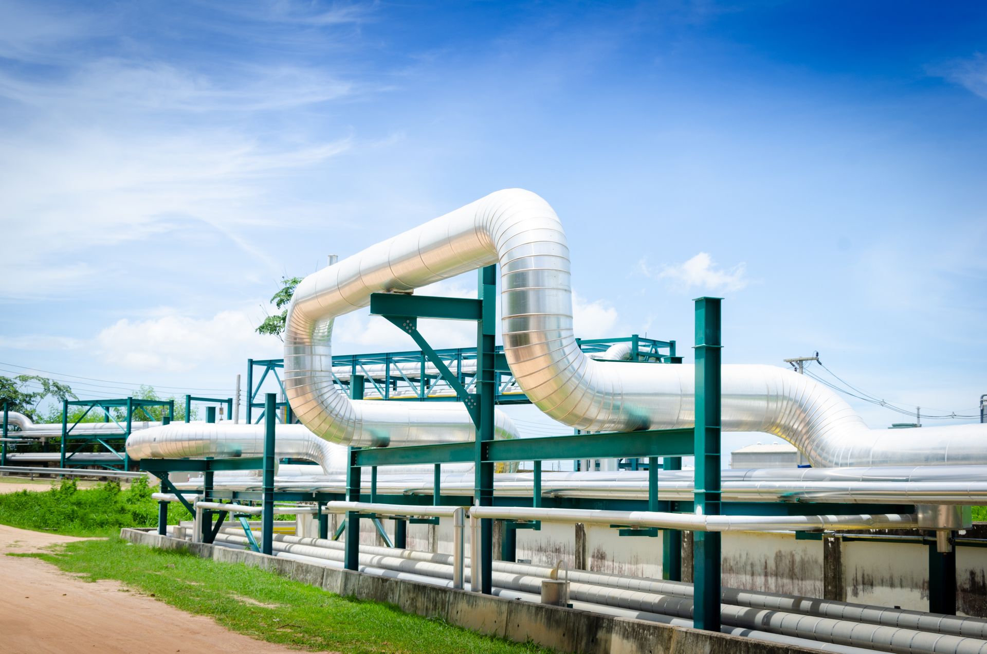
Installed performance is created by the complete assembly: substrate preparation, insulation layers, joints, vapour control, supports, cladding, penetrations, drainage and maintenance details.
A material with excellent laboratory properties can still underperform if the design conductivity is used incorrectly, joints open during thermal cycling, water enters through a termination, a support creates an uncontrolled thermal bridge, or maintenance access destroys vapour-barrier continuity.
ERATHERM therefore designs insulation as a coordinated engineering system. Calculated thermal performance is developed together with constructability, exposure, mechanical behaviour, corrosion risk, inspection access and the expected operating life.

The design basis records what the system must achieve, the conditions it must survive and the information that remains to be verified.
Controlled assumptions: Missing or uncertain inputs are listed in an assumptions and hold-point register instead of being hidden inside the design.
Changing one decision can alter layer temperatures, material suitability, support geometry, vapour control, cladding and maintenance requirements.
Heat loss or gain, surface temperature, process stability, condensation, freeze protection and cooldown or warm-up behaviour.
Design conductivity, temperature capability, layer arrangement, dimensional stability, compressive behaviour and compatibility.
Substrate coating, vapour-retarder continuity, water shedding, drainage, sealed terminations and inspectability.
Supports, shoes, rings, penetrations, cladding, fasteners, expansion or contraction zones and removable components.
Constructability, planned maintenance, replacement logic, energy economics, spares, inspection access and end-of-life decisions.
The required analysis is selected from the actual service and project acceptance criteria.
Steady-state thermal duty for flat, cylindrical and spherical geometries under defined ambient conditions.
Outer-surface prediction for process, personnel-contact and condensation-related criteria.
Temperature profile through multilayer systems to check each material, adhesive and membrane within its qualified range.
Surface margin, vapour diffusion and system continuity assessment for cold-service conditions where applicable.
Evaluation of supports, penetrations, metal paths and discontinuities that are not represented by one-dimensional field calculations.
Capital, energy, maintenance and replacement scenarios compared over the agreed study period and economic assumptions.
The exact build-up changes by service, but the design review follows the full path from the process boundary to the external environment.
Surface condition, preparation, coating compatibility and corrosion-control basis.
Product form, layer thickness, joints, interfaces and design-property basis.
Retarder, membrane, sealant, joint and penetration continuity where required.
Load transfer, compression control, movement and local heat-flow management.
Material, thickness, seams, overlaps, drainage, fastening and external exposure.
Removable areas, inspection ports, identification, hold points and reinstatement details.
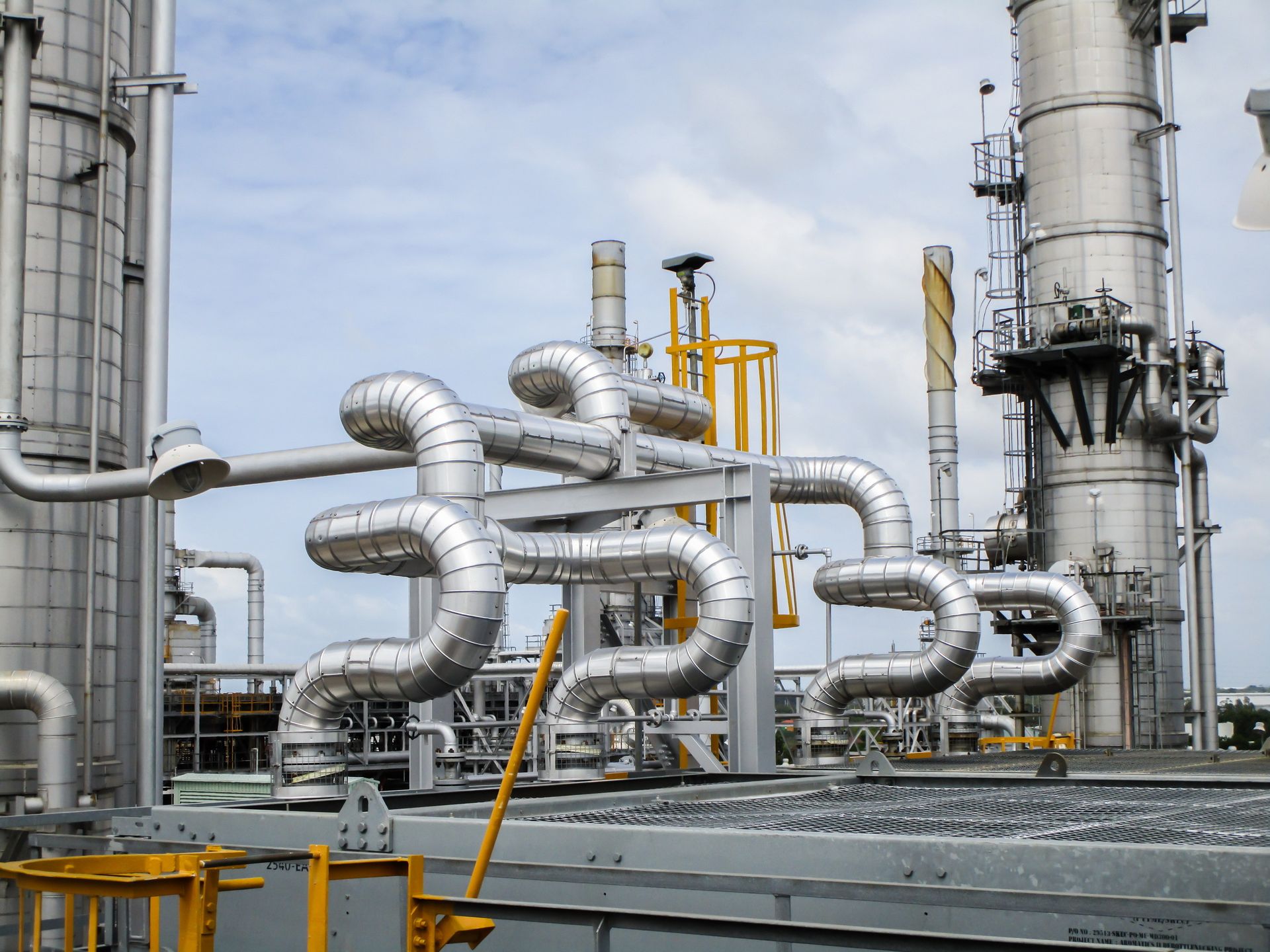
ERATHERM compares candidate systems using approved product data, relevant test methods and project conditions—not a universal “best material” ranking.
Thermal conductivity and maximum-use temperature are product-specific. Density, mean temperature, ageing, moisture, orientation and test method can change the value used in design. Final selection is therefore based on the approved manufacturer data and the project acceptance criteria.
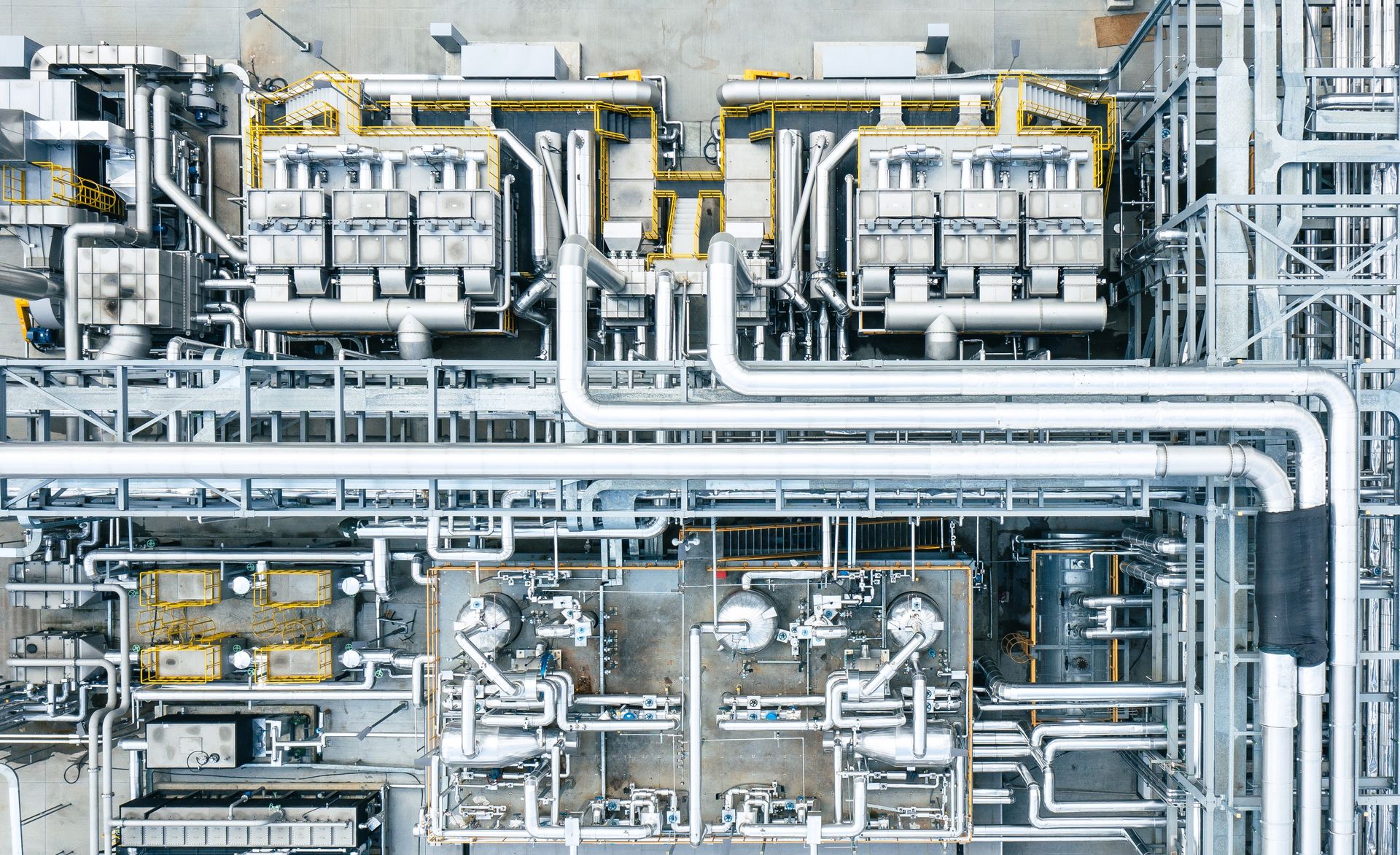
Process data, equipment, environment, specifications, responsibilities and missing inputs.
Thermal, condensation, safety, corrosion, maintenance and lifecycle acceptance criteria.
Heat flow, surface and layer temperatures, vapour control and sensitivity cases as required.
Candidate materials and architectures compared on performance, risk, constructability and cost.
Insulation, coating, vapour control, supports, cladding, joints and maintenance interfaces.
Design basis, calculations, specifications, typical details, schedules and QA/QC requirements.
Submittal review, site support, inspections, testing, deviations and as-built close-out.
The package is scaled to concept, FEED, tender, detail design, procurement, construction or brownfield-rehabilitation requirements.
Operating envelope, performance criteria, assumptions, exclusions, interfaces and document hierarchy.
Inputs, property basis, cases, heat flow, temperatures, condensation checks and sensitivities.
Option matrix, technical risks, material architecture and documented selection rationale.
Line or equipment duty linked to insulation build-up, cladding, vapour control and accessories.
Materials, qualification data, application requirements, tolerances, interfaces and acceptance criteria.
Joints, supports, penetrations, terminations, expansion zones, drainage and removable interfaces.
Engineering quantity structure, material descriptions, accessories, allowances and traceability rules.
Hold points, inspections, measurements, records, nonconformance control and close-out requirements.
System design establishes the rules; the dedicated shop-drawing service converts approved inputs into project-specific fabrication and installation drawings.
No single standard defines every insulation system. The governing edition, contractual hierarchy and project-specific acceptance criteria are confirmed in the design basis.
Industrial thermal-insulation guidance covering material selection, system design, protective coverings, application, inspection and maintenance.
ASTM C680-23aComputer-based estimates of heat gain or loss and surface temperatures for insulated flat, cylindrical and spherical systems.
ISO 12241:2022Calculation rules for heat-transfer-related properties of building equipment and industrial installations.
ISO 15758:2014Water-vapour diffusion calculation for cold-pipe insulation systems where its stated assumptions and temperature scope apply.
ISO 13732-1Assessment of human responses to contact with hot surfaces when touch-temperature criteria are required.
AMPP SP0198Systems approach to corrosion control under thermal insulation and fireproofing materials.
CINI ManualIndustrial insulation guidance, product specifications, system construction drawings and CUI-related practices.
Owner specifications, equipment data, piping and pressure-equipment codes, fire criteria and manufacturer instructions complete the framework.
Candidate products are compared against verified project duties and interfaces before the system is selected.
Field experience informs tolerances, access, water shedding, supports, sequencing and reinstatement requirements.
Engineering, calculation, material supply, fabrication, installation, inspection and verification can be managed under one scope.
Inputs, assumptions, selection rationale, revisions, hold points and acceptance records remain visible throughout the project.
It is the coordinated engineering of the complete installed assembly, including the substrate and coating interface, insulation materials and layers, vapour or moisture control, supports, cladding, joints, penetrations, removable areas and verification requirements.
A thickness calculation predicts defined thermal results under stated conditions. System design uses those results together with material behaviour, environmental exposure, corrosion risk, mechanical interfaces, installation, maintenance and lifecycle requirements to define a buildable and verifiable assembly.
Typical inputs include equipment geometry, operating and design temperatures, ambient conditions, process limits, insulation objectives, substrate and coating data, exposure, supports, maintenance requirements, design life, project standards and owner specifications.
Candidate systems are compared using approved product properties at the relevant temperature, moisture behaviour, mechanical resistance, chemical and substrate compatibility, fire requirements, constructability, maintenance needs, availability and lifecycle cost.
Yes. ERATHERM develops systems for hot service, cold and sub-ambient service, cryogenic and vacuum applications, cyclic equipment, heat-traced systems and combined thermal-acoustic duties. The calculation method and architecture are adapted to each service.
Condensation control combines an appropriate surface-temperature margin with low-permeance system selection, continuous vapour control, sealed joints and penetrations, thermally designed supports and installation QA/QC. Dew-point conditions and relevant diffusion assumptions are defined in the design basis.
The design considers substrate coating, material compatibility, water-entry paths, cladding seams, weatherproof terminations, drainage, inspection access, removable sections and the operating temperature profile. These measures reduce risk but do not replace an owner-specific inspection and maintenance programme.
Yes. Capital cost, energy value, operating profile, study period, discount assumptions, maintenance and replacement scenarios can be compared. The result is project-specific and should not be presented as a universal savings percentage.
Yes, when included in the agreed scope. The system design can define cladding materials and performance, support and thermal-break concepts, vapour-retarder continuity, joints, penetrations, expansion or contraction zones, drainage and maintainability requirements.
Yes. ERATHERM can provide a complete solution covering input review, calculations, system design, specifications, drawings, material supply, fabrication, field installation, QA/QC, commissioning support and as-built close-out.
Share your process temperatures, equipment list, drawings, environmental conditions and performance targets. ERATHERM will define the calculations, design package and delivery scope required for your project.