Multi-Layer Insulation (MLI) & Vacuum System Engineering
In cryogenic systems, a millimetric design error becomes a gigajoule-scale energy loss and a critical process-safety gap. With liquid hydrogen at −253 °C, liquid oxygen at −183 °C and liquid nitrogen at −196 °C, conventional insulation fails — the only answer is bringing multi-layer insulation (MLI) and vacuum technologies together in the right engineering language. ERATHERM blends field experience earned in satellite test-center TVAC chambers and large-scale cryogenic facilities with an academic engineering foundation — delivering MLI layer optimization, vacuum-jacketed piping (VJP), FEA thermal-shock analysis and outgassing-free material selection for aerospace, hydrogen and cryogenic systems.
 Space-Grade · Cryogenic
Where Conventional Insulation Collapses
At cryogenic temperatures, conventional mineral wool and elastomeric insulation has thermal conductivity that is simply not low enough — and more critically, it draws in moisture and air, losing up to 60% of its thermal performance and degrading over time.
- MLI — reflective aluminized films sandwiched with low-conductivity spacers under vacuum
- VJP — two concentric pipes, the annulus held under high vacuum with MLI inside
- Radiation nearly eliminated; conduction and convection minimized by vacuum
- The industry standard for hydrogen, helium, LOX and LNG transfer
LH₂ · LOX · LN₂ — Each With Its Own Design Criteria
A fluid's temperature, flammability and chemical activity directly drive MLI layer, material and safety design.
Hydrogen economy (green/blue H₂), rocket propulsion test systems, fusion research. NFPA 2 hydrogen safety code; CGA H-3 system standard; 40–80 MLI layer optimization; high-precision vacuum integrity.
Air separation units (ASU), medical oxygen, steel production, space propulsion. CGA G-4 oxygen safety; oxygen-compatible material selection; flammability-risk management; 20–50 MLI layer range.
TVAC test chambers, MRI systems, food freezing, laboratory cooling. EIGA Doc 33 vacuum guidance; standard 304L/316L inner pipe; asphyxiation-risk and venting management; 15–40 MLI layer range.
A Five-Stage Integrated Design Package
From thermal load to outgassing, from thermal-shock analysis to vapor barrier — every dimension in one engineering file.
01 · MLI Layer Optimization
Layer count (typically 10–80) and density directly affect heat transfer — but too many layers raise conduction. Optimum placement uses Lockheed-Martin-type semi-empirical models and modern CFD-supported analysis.
Detail engineering02 · Vacuum-Jacketed Piping (VJP) Design
Inner pipe (usually 304L/316L stainless), outer jacket, vacuum level (10⁻⁵–10⁻⁷ mbar), getter/sorbent placement, vacuum-life prediction and expansion-compensator design — delivered in one package.
03 · Thermal-Shock & Expansion (FEA)
At −253 °C a stainless pipe contracts by up to 0.3% — on a 100 m line that is 30 cm of physical movement. FEA-supported analysis sizes compensator position/type, supports and fixed/sliding anchors accordingly.
04 · Outgassing-Free Material Selection
Every vacuum material outgasses over time, degrading vacuum and insulation performance. ERATHERM selects ASTM E595 / ECSS-Q-ST-70-02C compliant materials (TML < 1%, CVCM < 0.1%) — mandatory for satellite and space systems.
Materials05 · Condensation & Icing Control
External condensation and icing on cryogenic surfaces cause corrosion and structural damage. Vapor-barrier design, dew point analysis and moisture-barrier selection are an integral part of the package.
Consultancy
Reflective Film + Spacer + Vacuum
The MLI sandwich is built on layer science — reflecting radiation while vacuum minimizes conduction and convection:
- Reflector film — Mylar/Kapton, double-aluminized PET or polyimide; ≥ 95% radiation reflection
- Spacer — Dacron net / fiberglass paper; low-conductivity, breaks the conduction bridge
- Vacuum — 10⁻⁵–10⁻⁷ mbar zeroing gas conduction and convection; held with getter/sorbent
- Layer count — 10–80, optimized to thermal load via Lockheed-type model + ANSYS/COMSOL
Six Engineering Components of a Vacuum-Jacketed Line
Each component is designed individually so the cryogenic fluid travels long distances with minimum heat loss.
304L/316L stainless in contact with the cryogenic fluid; material compatibility first.
Annular gap between inner and outer pipe, held at 10⁻⁵–10⁻⁷ mbar.
10–80 layers of multi-layer insulation placed within the vacuum space.
Chemicals that absorb gases accumulating in the vacuum, extending service life.
Bellows-type or sliding-joint mechanism absorbing thermal contraction.
Mechanical protection, environmental sealing and the vacuum boundary; carbon or stainless steel.
Material Selection That Holds Vacuum for Years
TML and CVCM values laboratory-verified to ASTM E595 and ECSS standards.
Total Mass Loss — the limit of total mass lost under vacuum.
Collected Volatile Condensable Materials — surface-condensation value.
NASA/ASTM joint under-vacuum outgassing test procedure.
European Space Agency material-compatibility standard.
From the Hydrogen Economy to Space Technologies
A rare team that has worked on site at some of the region's most critical cryogenic infrastructures.
Green/blue H₂ production and storage — the backbone of the hydrogen economy.
Air Separation Units producing LOX, LIN and argon.
Large terminals cooling natural gas to −162 °C.
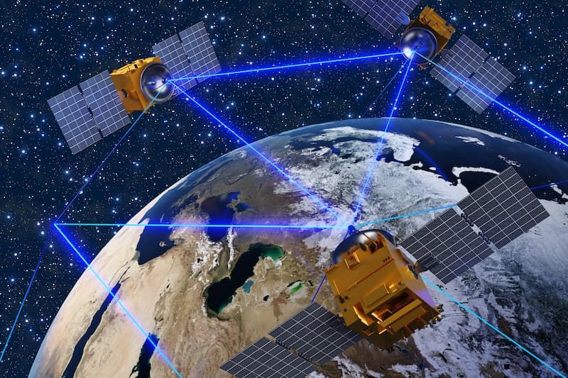
Vacuum + cold environment for satellite test and space simulation centers.
Military test systems and propulsion test infrastructure.
Helium systems at −269 °C for advanced research applications.
MRI devices, fusion-reactor magnets and particle-physics infrastructure.
Custom systems at academic-research and pilot-plant scale.
The International Cryogenic Engineering Framework
Multi-standard fluency and simulation-driven analysis in one engineering file.
Under-vacuum outgassing test procedure.
European Space Agency material standard.
Liquid hydrogen / liquid oxygen system standards.
Cryogenic vacuum insulation guidance.
Piping and pressure-vessel design.
Hydrogen safety code & metallic industrial piping.
CFD/FEA and multiphysics thermal-structural-vacuum analysis.
Cryogenic pipe-stress and flexibility analysis.
Python implementation of the Lockheed-Martin semi-empirical model.
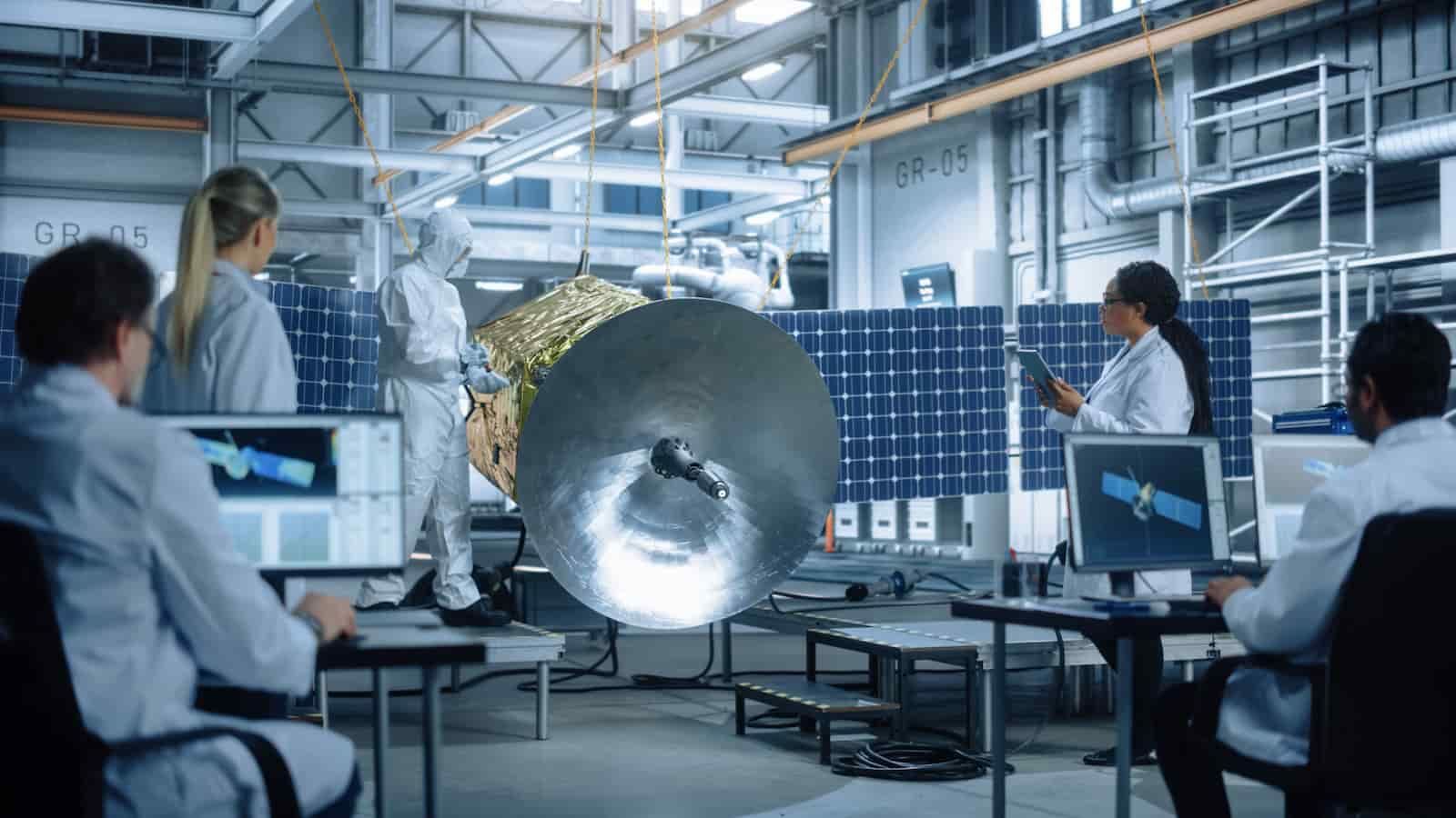
Satellite Test-Center TVAC Chambers
The TVAC (Thermal Vacuum) chambers of a national satellite test center simulate space conditions on the ground — high vacuum, extreme cold and hot environments — to perform qualification and acceptance testing of satellite components, representing one of the region's most critical space-infrastructure investments. ERATHERM took responsibility for cryogenic insulation engineering and field application on such a project: outgassing-free material selection, MLI layer optimization, vacuum integrity and combined thermal-vacuum performance, validated on site.
This is the most concrete example of our engineering office's desk work being tested in the field, with feedback flowing back into design. In cryogenic engineering, theory finding its match on site is something only teams that have actually applied field work on this kind of critical infrastructure can deliver.
Cryogenic & Vacuum Engineering Across Industry & Space
The MLI, vacuum and outgassing discipline behind ERATHERM's cryogenic work is the same engineering that supports long-term partnerships across energy, industrial and defense organizations.


From −269 °C helium systems to satellite-TVAC outgassing control, ERATHERM's references reflect a single standard of cryogenic engineering precision.
Six Decisive Advantages in Cryogenic Engineering
Cryogenic engineering is a field only a handful of firms worldwide can deliver with genuine field experience.
Drawing-board design grounded in MLI systems already applied on site.
Critical cryogenic infrastructure experience, including satellite TVAC test centers.
Dramatic heat-loss reduction versus equivalent conventional insulation.
ASTM, ECSS, CGA, NFPA, ASME, EIGA and EN in one file.
Contraction and stress analysis at −253 °C with finite elements.
Space-class selection at TML < 1%, CVCM < 0.1%.
Across the Space, Defense & Industrial Portfolio
MLI and vacuum engineering connect to ERATHERM's wider space, defense, nuclear and industrial thermal expertise.
Space · Defense · Nuclear
Engineering & Materials
MLI & Cryogenic Vacuum — Common Questions
What is Multi-Layer Insulation (MLI)?
MLI is an advanced insulation system that operates under vacuum, formed by sandwiching reflective aluminized thin films (Mylar, Kapton) with low-conductivity spacers (Dacron net, fiberglass paper). It almost entirely reflects radiation while vacuum minimizes conduction and convection.
Why does conventional insulation fail at cryogenic temperatures?
At cryogenic temperatures the thermal conductivity of conventional mineral wool or elastomeric materials is not low enough, and more critically they draw in moisture and air, reducing thermal performance by up to 60% and degrading over time. MLI under vacuum is the engineered alternative.
What is vacuum-jacketed piping (VJP)?
VJP consists of two concentric pipes whose annular space is held under high vacuum with MLI inside. It is the industry standard for hydrogen, helium, liquid oxygen and LNG transfer lines.
How many MLI layers are needed?
Typically 10–80 layers, optimized to each system's thermal load, vacuum level and geometry. Too many layers can increase solid conduction while too few admit radiation, so layer count and density are optimized with semi-empirical models and CFD/FEA analysis.
What does outgassing-free mean?
Every material in vacuum releases gas (outgassing) over time, degrading vacuum quality and insulation performance. ERATHERM selects materials compliant with ASTM E595 and ECSS-Q-ST-70-02C with TML < 1% and CVCM < 0.1% — mandatory for satellite and space systems.
Which fluids and facilities does this cover?
LH₂ (−253 °C), LOX (−183 °C), LN₂ (−196 °C), LNG and helium systems — across hydrogen production/storage, air separation units, LNG terminals, TVAC test chambers, defense test infrastructure, helium liquefaction, superconducting systems and cryogenic laboratories.
Get an MLI & Vacuum Engineering Package for Your Cryogenic System
For your LH₂, LN₂, LOX, LNG or helium systems, let's plan MLI layer optimization, VJP design and outgassing-free material selection together.