Eratherm İzolasyon A.Ş.
LNG terminals · Cryogenic engineering · Field execution

LNG Terminal Cryogenic Insulation Systems

Engineering, material selection, detailed design, supply, installation and QA/QC for LNG terminal tanks, transfer lines, jetties, marine interfaces, BOG systems and regasification equipment.

Heat-ingress controlCondensation preventionVapour-barrier continuityLayer-by-layer QA/QC
1,000,000+ m²Completed industrial insulation
20+ YearsEngineering and field experience
3 ContinentsEurope · Asia · Africa
End-to-EndDesign · Supply · Installation · QA/QC
Terminal-wide system engineering

Cryogenic Insulation Is a Terminal System, Not a Pipe Covering

LNG is typically stored and transferred at around −162°C under near-atmospheric conditions. At this temperature, every pipe support, flange, penetration, vapour stop and cladding termination becomes part of the thermal and moisture-control system.

A successful LNG terminal insulation design must limit heat ingress, maintain an external surface condition above the project-defined condensation threshold, accommodate thermal contraction and protect the cold system against long-term moisture entry. These requirements apply across unloading lines, jetty pipe racks, liquid and vapour-return systems, pumps, valves, BOG equipment and the cold end of regasification systems.

ERATHERM combines thermal analysis, material engineering, detailed design, procurement control, field installation and inspection under one coordinated engineering discipline. This continuity helps prevent design intent from being lost at interfaces or when critical layers become concealed.
Core principle: The selected insulation material is only one component. Vapour control, joints, supports, weather protection, workmanship and inspection determine the performance of the complete cryogenic system.
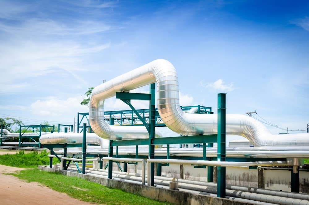
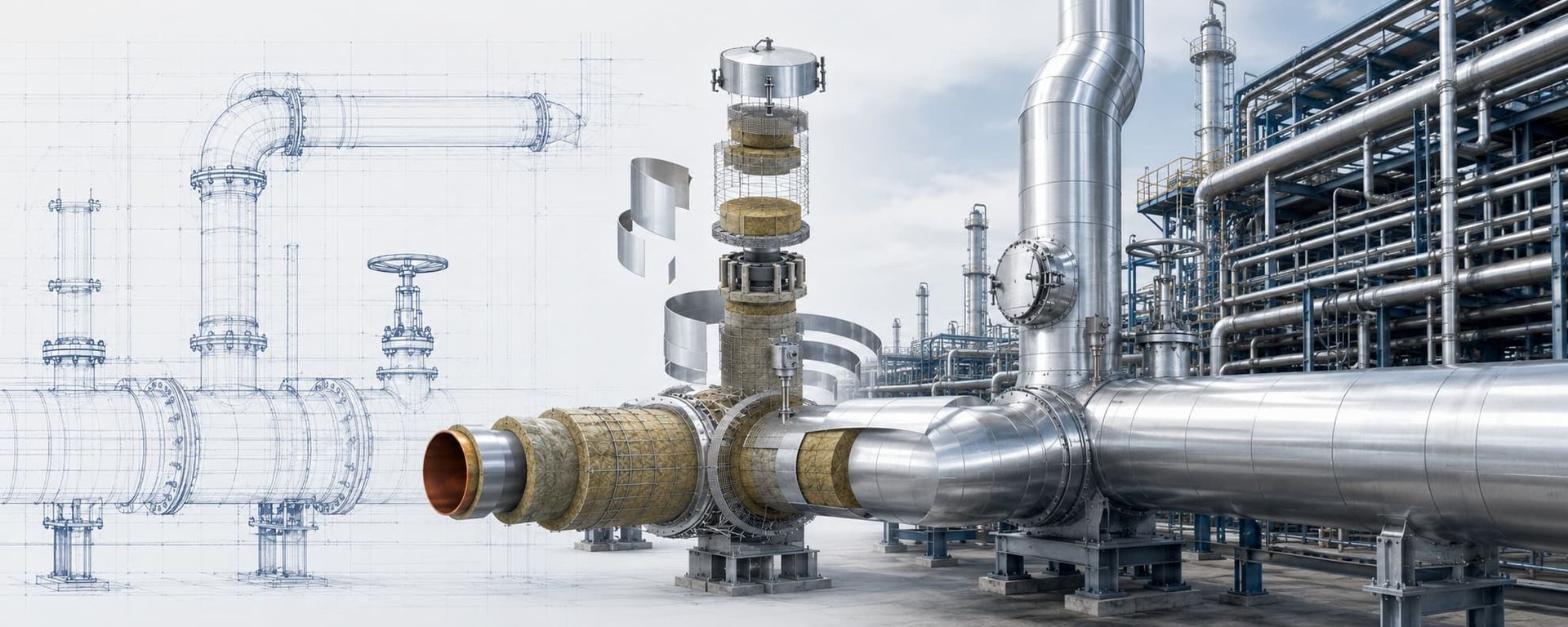
Industrial insulated piping and equipment illustrating terminal-wide insulation coordination
Terminal-wide coordination across pipework, equipment, supports, penetrations and weather barriers
Design drivers at cryogenic temperature

What the LNG Insulation System Must Control

LNG insulation is designed around interacting thermal, hygrothermal, mechanical and operational loads—not nominal thickness alone.

01

Heat Ingress

Conductive, convective and radiative heat transfer must be limited to the project duty and process performance targets.

02

Moisture Ingress

External water vapour is driven toward the cold surface; discontinuities can lead to condensation, ice and progressive system degradation.

03

Thermal Contraction

Pipe, equipment and insulation components contract during cooldown, requiring compatible joints, supports, closures and movement details.

04

Operational Interfaces

Valves, flanges, loading arms, ESD interfaces, supports and maintenance zones require performance without compromising access or operability.

LNG terminal insulation scope

From the Marine Interface to Regasification

The insulation architecture, vapour-control details and mechanical protection are adapted to each terminal zone and operating duty.

01 · Jetty

Unloading & Loading Lines

Long cryogenic transfer routes, pipe-rack interfaces, expansion movements, support details and marine weather exposure.

02 · Interface

Marine Loading Arms

Moving joints, swivel and maintenance interfaces coordinated with the equipment supplier and terminal operating philosophy.

03 · Return

Vapour-Return Pipework

Below-ambient gas service assessed for condensation control, operating cases, transitions and interface temperatures.

04 · Equipment

Pumps, Valves & Flanges

Close-fit insulation, sealed penetrations, removable details where justified, and controlled reinstatement after maintenance.

05 · Process

BOG Systems

Insulation for low-temperature boil-off gas equipment and piping, with service-specific surface and condensation criteria.

06 · Send-out

Regasification Cold End

Vaporizer inlet piping, cold interfaces and material transitions assessed across operating and standby scenarios.

07 · Storage

LNG Storage Interfaces

Tank penetrations, connected piping and boundary details coordinated with the dedicated tank insulation design.

08 · Floating

FSRU Interfaces

Compact layouts, vessel movement, marine exposure, maintainability and ship-to-shore interfaces integrated into the insulation basis.
Engineering translated into field details

Every Interface Must Preserve the Thermal Envelope

Engineering design review for piping insulation and equipment interfaces
Design basis, details, material selection and constructability review
Industrial piping insulation detail requiring joint and support coordination
Joints, supports, penetrations and equipment transitions
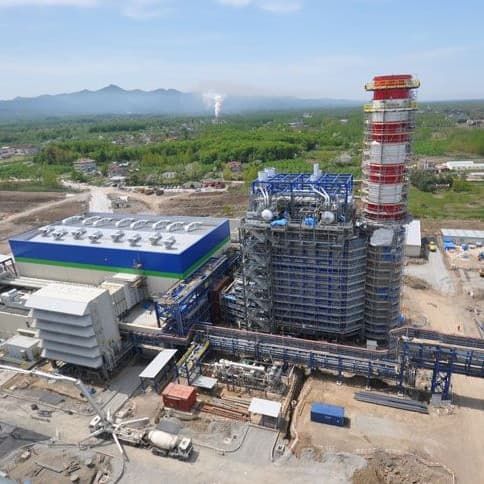
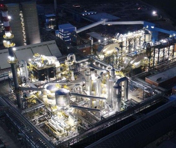
Large industrial facility illustrating coordinated installation planning
Integrated planning for large, schedule-critical work fronts
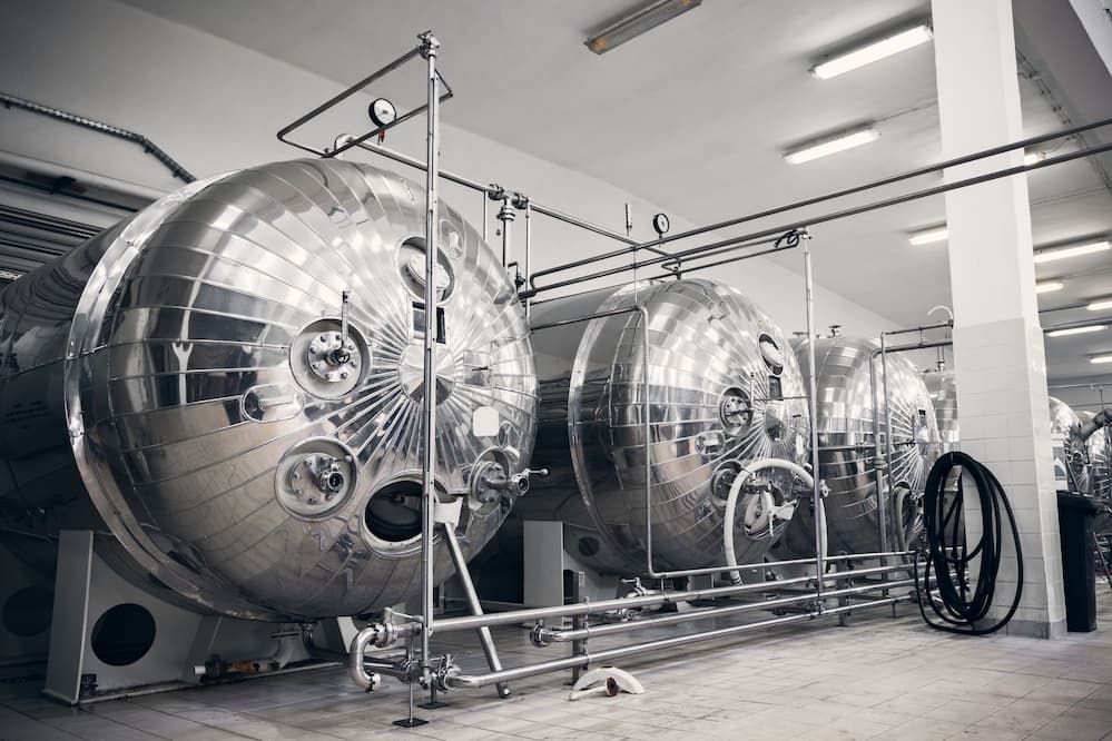
Cold-service vessels and piping representing cryogenic insulation system engineering
Cold and cryogenic insulation requires continuous vapour control and verified layer interfaces
Project-specific material engineering

Selecting the Insulation System for LNG Service

No material is selected by temperature alone. The design must also consider thermal conductivity over the service-temperature range, water-vapour behaviour, compressive load, contraction, fire strategy, mechanical exposure, geometry, installation sequence, maintenance and life-cycle risk.

ERATHERM evaluates individual and hybrid insulation systems against the project specification, approved manufacturer data and the geometry of the terminal asset. Layer count, joint layout, vapour-retarder location, support interfaces, cladding and sealant compatibility are defined as one system.

Selection boundary: The material descriptions below are engineering options, not universal prescriptions. Final selection requires project temperature, geometry, loads, environment, fire requirements and acceptance criteria.

Cellular Glass

Rigid system

Closed-cell inorganic insulation with high resistance to water and water-vapour transmission and useful compressive properties for selected cryogenic applications.

Design focus: joint treatment, layer staggering, load transfer, movement details, sealants, vapour barrier and outer protection.

PIR / PUR Systems

Low conductivity

Factory-produced rigid foam systems can provide efficient thermal performance where grade, density, dimensional stability, fire strategy and project approval are aligned.

Design focus: vapour-retarder continuity, contraction joints, fit-up, storage, facing compatibility and mechanical protection.

Cryogenic Aerogel Blankets

Flexible layer

Thin, flexible blanket systems may support complex geometry, space-constrained areas and selected maintenance-sensitive interfaces when qualified for the duty.

Design focus: compression control, layer arrangement, vapour control, closures, mechanical restraint and approved temperature range.

Hybrid Architectures

Engineered combination

Different materials may be combined to manage thermal, structural, geometric or maintenance requirements that a single material cannot efficiently satisfy.

Design focus: compatible interfaces, differential movement, continuous vapour resistance, constructability and inspection before concealment.

Thermal and hygrothermal verification

Calculations That Define the LNG Insulation Basis

The calculation model should reflect realistic operating modes, ambient design cases, geometry and thermal bridges—not only a one-dimensional pipe wall.

Heat GainSteady-state heat ingress through insulation, cladding, supports and defined thermal bridges under project ambient cases.
Surface TemperatureExternal surface condition and condensation-margin assessment using project humidity, wind, emissivity and operating assumptions.
Layer TemperaturesTemperature profile across multilayer systems for material qualification, interface review and vapour-control design.
Contraction & MovementAllowance for cooldown displacement, contraction joints, terminations and insulation closure details around moving interfaces.
Thermal BridgesSupports, shoes, nozzles, penetrations, valves and structural interfaces assessed for local cold-surface and heat-leak risk.
Process InterfaceInsulation heat ingress is coordinated with the project process basis and specified BOG or equipment-performance targets.
Performance statement: Insulation limits heat ingress and supports the specified process or boil-off target; it does not eliminate all heat transfer or all boil-off.
One coordinated delivery model

From Design Basis to Commissioning Verification

ERATHERM can support a defined technical package or manage the complete insulation scope through engineering, supply and site execution.

01Inputs & Design BasisP&IDs, line list, temperatures, ambient cases, layouts, specifications and operating modes.
02Analysis & SelectionHeat gain, surface temperature, condensation, materials, thickness and system architecture.
03Detail EngineeringTypical details, supports, vapour stops, terminations, BOM/MTO, specification and ITP.
04Supply & TraceabilityTechnical submittals, material approval, certificates, receiving checks and controlled storage.
05Field InstallationQualified execution, joint control, vapour-barrier continuity, cladding and work-front coordination.
06QA/QC & Close-OutHold points, concealed-layer inspection, NCR closure, final walkdown and quality dossier.
Cold-service detail control

Critical Details for LNG Transfer Lines and Equipment

Many cryogenic failures begin at local interfaces rather than in straight pipe runs. Drawings and work instructions must show how the thermal envelope and vapour-control layer continue through supports, penetrations, valves, flanges and equipment boundaries.
  • Staggered joints in multilayer systems
  • Vapour-retarder continuity and sealed penetrations
  • Vapour stops, terminations and compartmentalisation where specified
  • Pipe shoes, supports and load-bearing insulation details
  • Thermal contraction gaps and movement-compatible closures
  • Valves, flanges and removable access details
  • Cladding laps, drainage direction, sealants and marine exposure
  • Transitions between cryogenic, cold and ambient-temperature zones
Inspection rule: Quality must be verified before each critical layer becomes concealed. Final walkdown alone cannot confirm joint fit, layer sequence or vapour-barrier continuity.
Engineering-supported verification of industrial insulation interfaces and performance
Engineering details must remain constructible, inspectable and maintainable in real terminal conditions
Onshore and floating terminal contexts

Onshore LNG Terminal and FSRU Insulation Considerations

The same cryogenic principles apply, but layout, movement, access, weather and interface constraints change the system details.

Design AreaOnshore LNG TerminalFSRU / Floating InterfaceInsulation Engineering Response
LayoutLong pipe racks, jetty routes and distributed process areasCompact, congested equipment and short maintenance clearancesGeometry-specific layer build-up, prefabrication strategy and access review
MovementThermal growth, settlement and pipe-support displacementThermal movement combined with vessel motion and flexible interfacesMovement-compatible joints, terminations, supports and equipment boundaries
EnvironmentSite-specific wind, rain, solar load and coastal exposurePersistent marine atmosphere, spray, vibration and vessel operating conditionsProject-qualified cladding, fasteners, sealants, drainage and mechanical protection
MaintenancePlanned access across multiple terminal work frontsRestricted space and high value of rapid reinstatementMaintainable details, controlled removal, inspection and documented reinstatement
InterfaceJetty, loading arm, tank and regasification boundariesShip-to-shore, turret or transfer-system boundaries as applicableClear scope breaks, responsibility matrix and coordinated interface drawings

Actual FSRU scope depends on vessel class, terminal concept, project specification, equipment-vendor requirements and applicable regulatory or classification rules.

Layer-by-layer quality assurance

LNG Terminal Insulation QA/QC and Commissioning Support

Cold performance depends on documented inspection before concealment, disciplined closure of nonconformities and stable-operation verification after startup.

01

Material Receiving

Approved product identity, grade, batch, certificates, thickness, dimensions, damage, moisture condition, shelf life and protected storage.

02

Pre-Insulation Release

Surface and coating release, NDT completion, tracing status, support readiness, cleanliness, dryness and access for installation.

03

In-Process Inspection

Layer sequence, thickness, staggered joints, gaps, compression, bands, supports, vapour barrier, stops, terminations and cladding.

04

Hold & Witness Points

Project-defined inspection releases before critical layers, vapour barriers or finished weather protection are concealed.

05

NCR & Punch Control

Traceable nonconformity, corrective action, reinspection, close-out evidence and final work-front acceptance.

06

Post-Startup Verification

Condensation, frosting and cold-spot screening after stable operation, supported by suitable ambient and process records.

Thermography boundary: Infrared screening can help identify thermal anomalies after commissioning, but emissivity, reflections, wind, ambient conditions and process load affect results. It complements rather than replaces layer-by-layer inspection.
Project-governed reference framework

Standards Are Applied Through the Contract Design Basis

The governing sequence is the contract, project specification, approved drawings and data sheets, manufacturer instructions, approved method statement and ITP, followed by referenced standards.

EN 1473:2021Reference framework for design of onshore LNG installations.
EN 14620 SeriesProject-relevant framework for site-built, vertical, cylindrical, flat-bottomed refrigerated storage tanks.
ISO 16903:2015LNG characteristics and materials relevant to cryogenic handling.
ISO 16904:2016 & ISO 28460:2010Marine transfer arms and ship-to-shore LNG interface considerations.
ISO 20257-2:2021Project-relevant design considerations for floating LNG installations.
Engineering deliverables

Audit-Ready Technical and Quality Records

Design BasisCriteria, inputs, assumptions and system boundaries
Thermal CalculationsHeat gain, surface and layer temperatures
Material MatrixService-by-service system and thickness schedule
Typical DetailsSupports, joints, stops, valves and terminations
BOM / MTOInsulation, barriers, cladding and accessories
Method StatementInstallation sequence and interface controls
ITP & ChecklistsHold, witness, surveillance and records
Quality DossierMIR/WIR, reports, NCR, punch and close-out
Engineering backed by execution

Proven Industrial Field Experience

ERATHERM brings more than 20 years of engineering and field experience to high-temperature, cold, cryogenic and specialised insulation systems. Its capabilities span calculations, system design, specifications, material supply, prefabrication, site installation, supervision, QA/QC and performance verification.

Experience has been developed on international critical-facility and EPC projects involving organisations such as ExxonMobil, SOCAR, STAR Refinery, RWE, OMV, Técnicas Reunidas, SAIPEM, TÜPRAŞ, Tekfen, ENKA, GE, Siemens and METKA. These names describe broader industrial project experience and are not presented as LNG-specific client references.
1,000,000+ m²Completed insulation across industrial assets
15,000+ MWPower-plant project experience
20+ YearsEngineering and application know-how
Single DisciplineCalculate → Design → Supply → Install → Verify
Frequently asked questions

LNG Terminal Cryogenic Insulation FAQ

What is LNG terminal cryogenic insulation?
It is the engineered thermal, vapour-control and mechanical-protection system applied to LNG terminal tanks, transfer lines, jetties, equipment and cold process interfaces. Its purpose is to limit heat ingress, control external condensation or icing, accommodate thermal contraction and protect long-term performance.
What temperature is LNG insulation designed for?
LNG is typically stored and transferred at around −162°C under near-atmospheric conditions, although the design temperature must come from the project process data, operating cases and specification. Materials and accessories are qualified for their actual position and temperature within the complete system.
Which LNG terminal equipment requires cryogenic insulation?
Typical scope includes unloading and loading lines, jetty piping, marine loading-arm interfaces, liquid and vapour-return pipework, pumps, valves, flanges, BOG equipment, tank connections and the cold end of regasification systems. The exact battery limits are project-defined.
Which insulation material is best for LNG piping?
There is no universal best material. Cellular glass, qualified PIR/PUR, cryogenic aerogel blankets and hybrid systems may be considered depending on temperature, geometry, loads, moisture behaviour, fire strategy, mechanical exposure, maintenance, project approval and life-cycle objectives.
How does insulation support LNG boil-off control?
The insulation system limits heat entering the LNG equipment or piping and therefore supports the heat-ingress and boil-off targets defined by the process design. It does not eliminate all heat transfer or all boil-off, and the overall BOG rate depends on the complete storage and operating system.
Why is vapour-barrier continuity critical in LNG service?
The cold system creates a strong water-vapour drive from the ambient environment toward the cold surface. Gaps at joints, supports or penetrations can allow condensation and ice formation inside the insulation, degrading thermal performance and potentially damaging components.
How is LNG insulation thickness calculated?
Thickness is evaluated using project temperatures, geometry, thermal-conductivity data over the relevant temperature range, ambient temperature and humidity, wind, emissivity, heat-gain limits, surface-temperature or condensation criteria, thermal bridges and applicable safety margins.
Can ERATHERM provide both engineering and field installation?
Yes. ERATHERM can provide thermal calculations, material selection, detail engineering, specifications, BOM/MTO, procurement support, prefabrication, site installation, supervision, QA/QC, turnover documentation and post-start-up performance screening as a coordinated scope.
Is FSRU insulation the same as an onshore LNG terminal?
The same cryogenic heat- and moisture-control principles apply, but FSRU layouts add vessel movement, compact access, vibration, marine exposure, classification requirements and specialised ship-to-shore interfaces. These conditions must be reflected in the project-specific details.
Design the complete thermal envelope

Plan Your LNG Terminal Insulation Scope with ERATHERM

Share your line list, process temperatures, layouts, project specification and operating cases. Our engineers can define the calculation basis, material architecture, details, supply scope, field execution and QA/QC plan.

Final insulation design, materials, thicknesses, details and standards are project-specific and must be verified against the contract, process conditions, approved documents, manufacturer data and applicable regulations. Standards listed on this page are a reference framework, not a claim that every standard applies to every project. Company names describe ERATHERM's wider experience on projects involving those organisations and do not imply endorsement, current affiliation, an LNG-specific reference or a direct contractual relationship in every case.