
Solar Radiation
Incident solar flux changes with geometry, orientation, season and mission attitude, creating surface-specific absorbed loads.
Mission-specific thermal engineering for satellites and spacecraft—from orbital hot and cold cases to MLI blanket architecture, electronics stabilization, detailed integration and TVAC-supported verification.
In orbital vacuum, a spacecraft does not reject heat to the external environment through normal atmospheric convection. Its temperature is governed by absorbed solar energy, planetary albedo and infrared radiation, internal equipment dissipation, conduction through the structure and radiation from external surfaces.
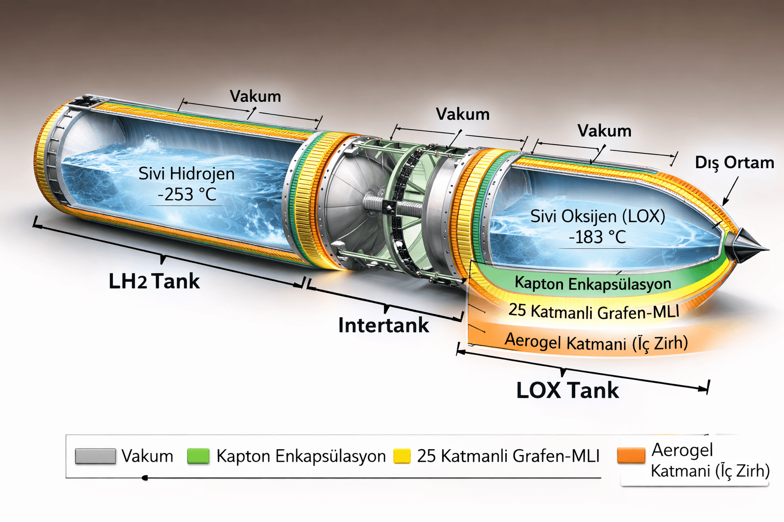
Multi-layer insulation (MLI) limits radiative heat exchange across selected surfaces. It does not replace the conductive heat path that transports electronics dissipation to a radiator, nor does it replace heaters required during cold mission modes. MLI, radiators, coatings, interfaces, straps, heat pipes, heaters and sensors must therefore be designed as one thermal-control architecture.
ERATHERM develops this architecture from mission inputs and component limits through analysis, MLI detail engineering, integration documentation and thermal-vacuum verification support.
A credible satellite thermal-control system is based on orbit, attitude, mission modes and equipment power profiles—not one steady operating temperature.
Incident solar flux changes with geometry, orientation, season and mission attitude, creating surface-specific absorbed loads.
Reflected sunlight and planetary infrared radiation add orbit-dependent external loads that vary with view and altitude.
Transitions between sunlight, eclipse, safe mode and operational modes create transient cold and hot conditions.
Avionics, payloads, batteries, RF units and power electronics release different heat loads according to duty cycle.
MLI reduces unwanted radiative exchange, while dissipated heat still needs a controlled path from the source to a surface that can reject it to space.
Mode-dependent dissipation and allowable component temperatures.
Contact conductance, flatness, preload and interface material.
Conductive heat spreading and controlled transport.
Area, orientation, optical properties and view to space.
Protection against external loads and cold-case excursions.
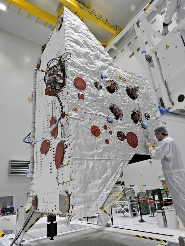
Satellite MLI insulation is a lightweight blanket system of low-emittance reflective layers separated by low-conductance spacers and protected by mission-appropriate outer and inner covers. Layer architecture is selected together with mass, geometry, venting, contamination, optical and integration requirements.
More MLI layers do not automatically create better performance. Excessive layer density, local compression, metallic contact, poorly controlled seams, penetrations and fasteners can create thermal short circuits that materially reduce effective performance.
ERATHERM translates the thermal model into blanket zones, layer schedules, manufacturing patterns, closures, exclusion zones, attachment details and an as-built configuration that can be inspected and correlated with test results.
The model and the manufactured blanket must describe the same thermal configuration, including real interfaces and workmanship-sensitive areas.
Mission-compatible films, deposited surfaces, spacer media and protective covers selected for optical, thermal, mechanical and contamination requirements.
Layer arrangement balanced against effective emittance, blanket thickness, mass budget, manufacturability and compression sensitivity.
Controlled gas release during ascent and pump-down without uncontrolled billowing, trapped volumes or damage to blanket geometry.
Overlap direction, edge finish and local closures designed to limit radiative openings and conductive bridges.
Purpose-designed details around sensors, radiators, thrusters, antennas, connectors, harnesses and mechanical interfaces.
Fastener layout, local reinforcement, isolation and access coordinated without excessive blanket compression or contact.
Electrical continuity and grounding provisions coordinated with spacecraft EMC, charging and customer requirements.
Approved materials, handling, identification, workmanship inspection and as-built configuration control for verification.
The correct mix of passive and active devices depends on thermal limits, gradients, stability, available power, radiator area and mission operating modes.
External heat absorption, internal radiative coupling and heat rejection managed through zoning, surface properties and view to space.
Thermal interface materials, structural paths, doublers and flexible straps distribute or isolate heat where required.
Passive transport options considered where long heat paths, local heat density or radiator placement require enhanced transfer.
Survival and operational heaters sized against cold cases, control thresholds, duty cycle, redundancy and available power.
Sensor type and location planned around control, flight monitoring and meaningful correlation of analysis and test results.
Low-conductance interfaces reduce parasitic heat flow while being checked against structural load, alignment and integration constraints.
Thermal stabilization means maintaining equipment within its permitted temperature range, gradient and stability band throughout operation, standby, eclipse and survival modes. Depending on the case, the solution may need to remove heat, retain heat or add controlled heater power.
Equipment dissipation is mapped by mission mode and duty cycle. Mounting interfaces, nearby heat sources, harness conduction, allowable temperatures, radiator access and heater-power limits are then assessed together rather than as isolated component values.
The thermal model converts mission geometry, surface properties, conductive interfaces and equipment power profiles into component-level temperature predictions.
The package can be tailored from an independent design review to a coordinated thermal-control and MLI engineering scope.
MLI engineering becomes usable when the analysis is converted into manufacturable blanket geometry and controlled interfaces. Deliverables can include zoning plans, CAD layouts, cutting patterns, material schedules, seam and overlap details, attachment points, aperture details, radiator and sensor exclusion zones, harness interfaces and installation sequences.
Blanket identification, revision status and as-built configuration are retained so the installed hardware can be compared with the model and test article. Removal and reinstallation instructions can be defined for access-sensitive areas.
The thermal-control architecture is matured with the spacecraft design and retained as a traceable chain from requirement to verified configuration.
Verification confirms both the hardware configuration and the model's ability to predict temperatures under representative boundary conditions.
Material approval, outgassing documentation, cleanliness, layer count, seams, overlaps, attachments and configuration inspection.
Test cases, chamber boundaries, sensor locations and power modes planned to exercise critical thermal-control functions.
Predicted and measured temperatures compared, uncertain parameters adjusted within justified ranges and the model updated.
Applicable standards are selected through the contract, mission assurance plan and customer requirements. They are used as project reference frameworks, not presented as a claim that every standard applies to every spacecraft or that a specific hardware configuration is automatically flight-qualified.
The governing sequence is the contract and mission requirements, approved spacecraft data and interfaces, approved materials and processes, analysis and verification plan, followed by applicable ECSS, customer or agency documents.
ERATHERM combines more than 20 years of thermal engineering with vacuum, MLI, cryogenic and satellite test-infrastructure experience. Capabilities include thermal analysis, detail engineering, material and interface definition, integration planning, inspection and verification support.
Share the orbit and mission modes, spacecraft geometry, component temperature limits, dissipation profiles, interfaces and verification philosophy. Our engineers can define the analysis basis, thermal-control architecture, MLI details and TVAC-supported verification plan.
Final thermal-control architecture, MLI materials, blanket details, margins, verification methods and standards are mission- and project-specific and must be confirmed against the contract, customer requirements, approved spacecraft data, manufacturer information and applicable product-assurance rules. References on this page are a technical framework, not a claim that every standard applies to every project. This page does not claim flight-proven hardware, flight qualification or in-orbit heritage unless documented for a defined mission and configuration.