Boundary conditions
Orbit cycles, flight profiles, hydrostatic pressure or facility operating cases inform conductive, radiative, convective and transient models.
Defence · Aerospace · Space
From spacecraft and UAVs to hypersonic test systems, submarines and protected facilities, we manage heat flow, cryogenic interfaces, acoustic loads and infrared signatures at system level. Analysis, materials, integration and test acceptance follow one traceable chain of requirements.
Engineering approach
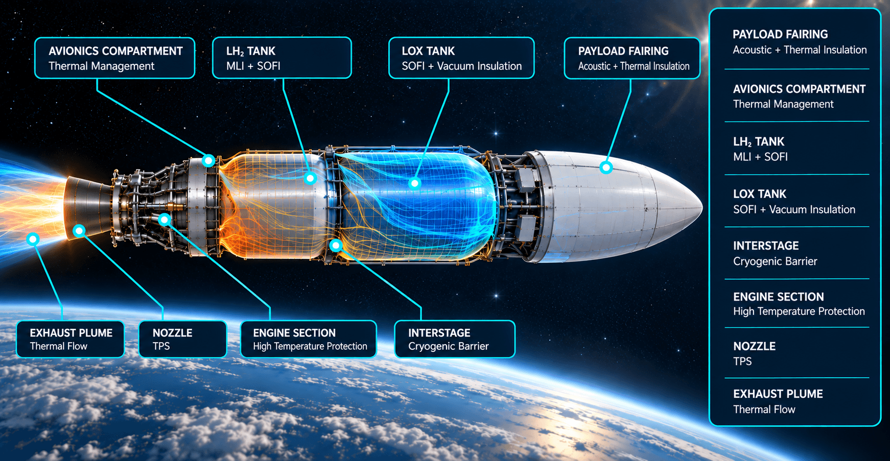
We select materials against mission duration, heat flux, vacuum, mass, vibration, fire, contamination and acceptance criteria as well as operating temperature.
Orbit cycles, flight profiles, hydrostatic pressure or facility operating cases inform conductive, radiative, convective and transient models.
MLI, vacuum, thermal bridges, acoustic lining, sealed penetrations and maintenance access are resolved in the same design.
Thermal-vacuum (TVAC), thermography, temperature sensors and environmental tests allow models to be compared with installed performance.
Project confidentiality. Platform, mission, geometry and performance data are handled under an agreed access matrix and non-disclosure agreement (NDA).
Explore the programme map
Twelve application areas are organised into three programme groups. Each technical page addresses the platform's heat paths, material architecture and verification approach.
ASpace, satellites and test infrastructure
01Spacecraft and Satellite Thermal Engineering Orbital cycles, radiators, heat pipes and thermal balance. 02Vacuum and MLI Systems Multi-layer insulation, vacuum-jacketed piping and cryogenic tanks. 03Wind Tunnels and Test Infrastructure (Turkish-language page) Exhaust silencers, hot-gas ducts and test-facility acoustics. 04Thermal Vacuum (TVAC) Chambers Shroud and cold-wall design, parasitic heat paths, model correlation.BAerospace and weapon systems
05UAV/UCAV Thermal Engineering Avionics, batteries, exhaust and payload heat paths. 06Missile and Hypersonic Systems Thermal protection, hot sections, radome interfaces and test stands. 07Laser and Directed Energy (Turkish-language page) High heat flux, cooling interfaces and optical stability. 08UAV Thermal Test Chambers Environmental test rooms, temperature uniformity and envelope design.CNaval and critical facilities
09Ship and Submarine Systems Acoustic signatures, machinery isolation and thermal zoning. 10IR Signature Management for Military Facilities (Turkish-language page) Envelope contrast, ventilation and exhaust, MWIR/LWIR measurements. 11CBRN-Protected Structures (Turkish-language page) Sealed envelopes, filtered HVAC penetrations, fire and condensation. 12Critical and Data Facilities Secure compute halls, cooling distribution and condensation control.Engineering and support
Our platform solutions share a delivery model, material selection discipline and verification method. The pages below explain scope, materials and acceptance in more detail.
Scope
Work packages range from independent engineering to turnkey integration, including R&D collaboration, technical training and framework consultancy.
Explore delivery models (Turkish-language page)Materials
MLI, aerogel, microporous and ceramic-fibre systems selected for mission conditions, with lot traceability and alternative sourcing plans.
Explore material architecture (Turkish-language page)Acceptance
Thermal-balance and TVAC test plans, sensor and uncertainty budgets, model–test correlation and acceptance documentation.
Explore verification (Turkish-language page)Platform focus
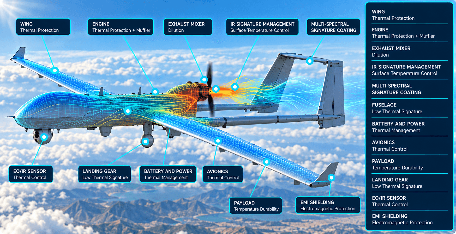
Exhaust, airframe, avionics, power electronics and payload heat paths interact; IR signature targets are assessed against the defined mission band.
UAV/UCAV technical page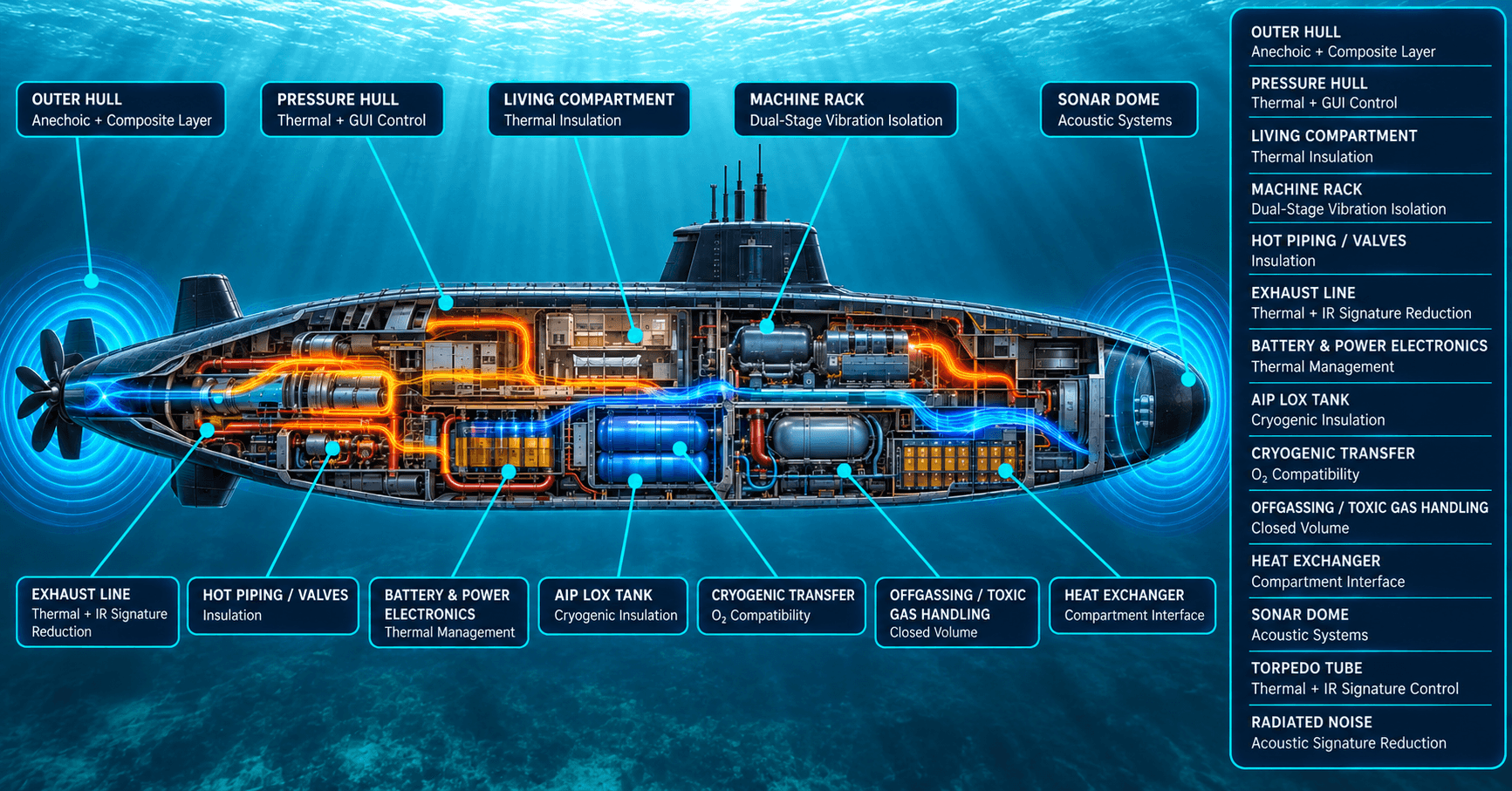
Machinery-borne acoustic signatures, hot piping and exhaust zones, condensation and enclosed-space safety are considered together.
Ship and submarine technical page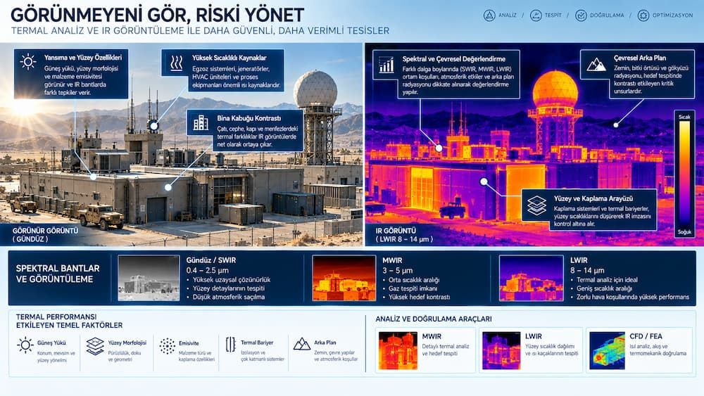
Solar loading, internal heat sources, ventilation outlets and structural bridges are evaluated through MWIR/LWIR measurements and model correlation.
Military facility technical page (Turkish-language page)Delivery chain
Standards considered
Standards do not apply automatically to a product: their scope must be defined against customer requirements and configuration in the project specification. Further details: Testing, Verification and Qualification (Turkish-language page).
Frequently asked questions
No. Multi-layer insulation (MLI) relies on high vacuum for its radiative performance. At atmospheric pressure, gas conduction between layers becomes significant; layer compression, spacers and penetrations add to the total heat leak.
No. The shroud, cold wall, supports, cable and fluid penetrations and test fixture all affect the total heat load. These parasitic paths are modelled in the test plan and included in the measurement uncertainty budget. Verification approach → (Turkish-language page)
First, define the sensor band (MWIR/LWIR), viewing geometry, mission or operating profile and environmental background. Then compare thermography, contact temperature measurements and the numerical model against project-specific acceptance criteria.
Catalogue data are only a starting point. Suitability is verified against the application specification through outgassing (ASTM E595), cleanliness, flammability and oxygen compatibility, mechanical environment, lot traceability and required material or subsystem testing. Materials page → (Turkish-language page)
Yes. If the requirements matrix and handover interfaces are clear, separate scopes can be prepared for engineering alone, material procurement, manufacture and field integration, or model–test correlation. Delivery models → (Turkish-language page)
Share platform or facility geometry, heat loads, environmental limits, interfaces and test objectives. We will define a practical scope together. Sensitive project data are received only after an NDA is in place.