
System design and layer build-up
Material family, layer sequence, joint stagger, vapour barrier position and cladding strategy selected together against the cold face temperature and the moisture drive.

In cryogenic service the failure is invisible from the outside. A break in vapour barrier continuity, a cold bridge at a support, a seam detailed for ambient service: each turns into ice, into boil-off and into corrosion long before anything is visible on the cladding. ERATHERM designs cryogenic insulation systems from the thermodynamics outward, covering multi-layer insulation build-up, vacuum jacket interfaces, vapour barrier seam detailing and contraction allowance. The same discipline runs through LNG terminals, air separation plants, liquid hydrogen systems and thermal vacuum test chambers. We work worldwide, in EPC-level English.
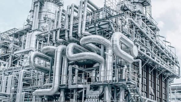
Cryogenic design is decided by continuity, not by thickness. Each package below is defined by the interface it has to protect and the data required to design it.
Material family, layer sequence, joint stagger, vapour barrier position and cladding strategy selected together against the cold face temperature and the moisture drive.
Reflector and spacer selection, layer count, layer density, seam and penetration treatment, and the compression limits that decide whether the calculated performance is ever achieved.
Jacket penetrations, getter and pump-out port arrangement, support standoffs, warm-to-cold transitions and the thermal shorts that dominate the heat budget.
Continuous barrier strategy, seam overlap, sealant and mastic selection, termination at supports, nozzles and manways, and the inspection route that proves continuity.
Contraction joint spacing, slip layers, oversized sleeves and support movement allowance for the full cooldown range, not for the ambient installed condition.
Heat in-leak by path: insulation, supports, nozzles, instrumentation and penetrations, summed into a boil-off figure that can be compared with the process guarantee.
Cryogenic thermal conductivity is taken at the mean service temperature from the manufacturer's measured data, never from an ambient catalogue value.
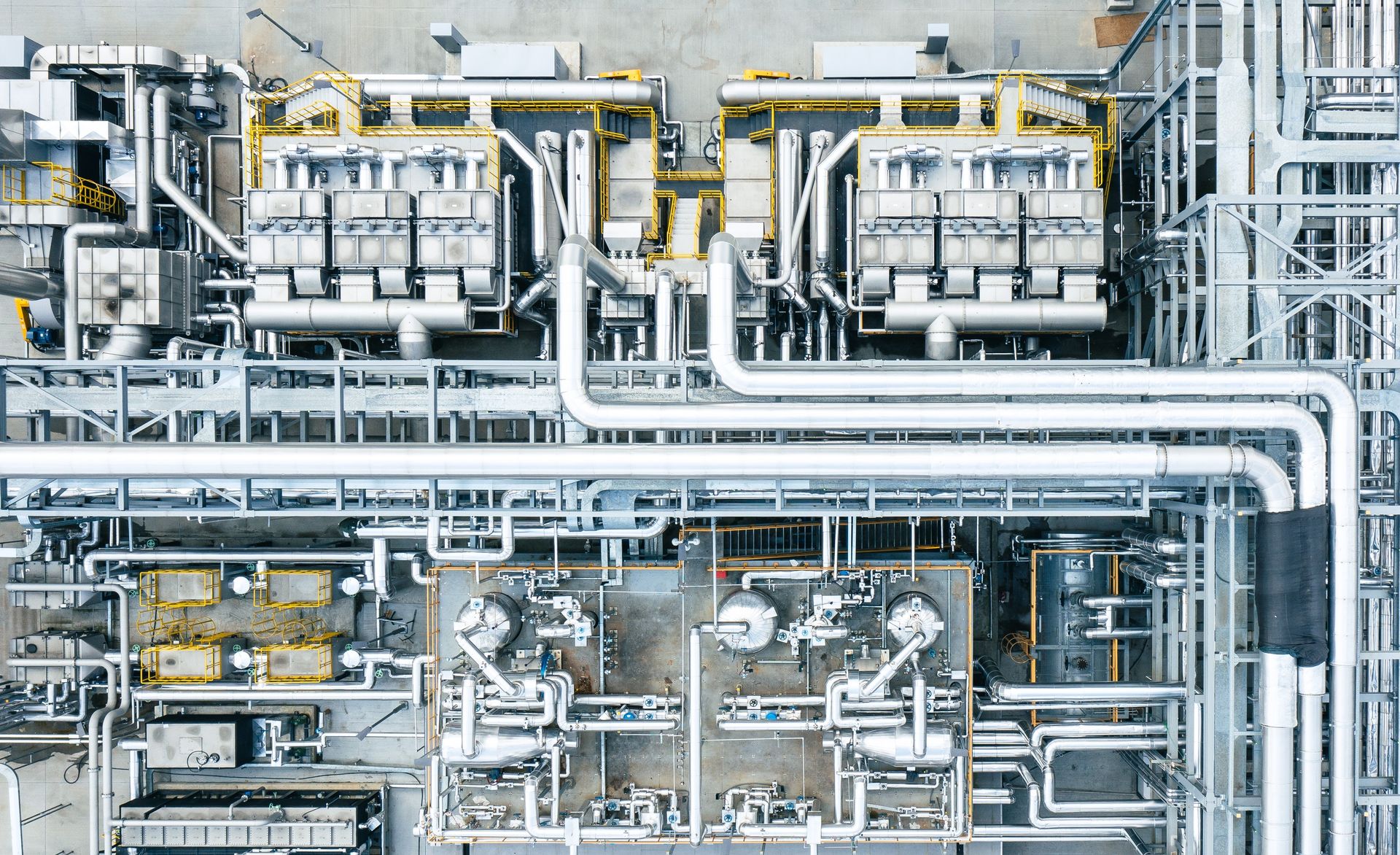
The vapour pressure difference across a cryogenic insulation system is enormous and it always drives inward. Any discontinuity in the barrier draws water vapour into the layer, where it freezes, expands and destroys the structure from inside.
So the first design decision is not the material. It is where the barrier sits, how it is terminated at every interruption, and how it will be inspected before the cladding goes on.
Produced under your document control procedure, in EPC-level English, revision controlled.
Heat in-leak by path, surface temperature, cold face condition and the boil-off estimate.
Layer sequence, material families, barrier strategy and cladding, with justification.
Reflector and spacer build, layer count, compression limits, seam and penetration treatment.
Supports, contraction joints, penetrations, terminations and vacuum jacket interfaces.
Sequence, handling, environmental limits and the hold points that protect the barrier.
Continuity checks, thickness verification, cooldown monitoring and acceptance criteria.
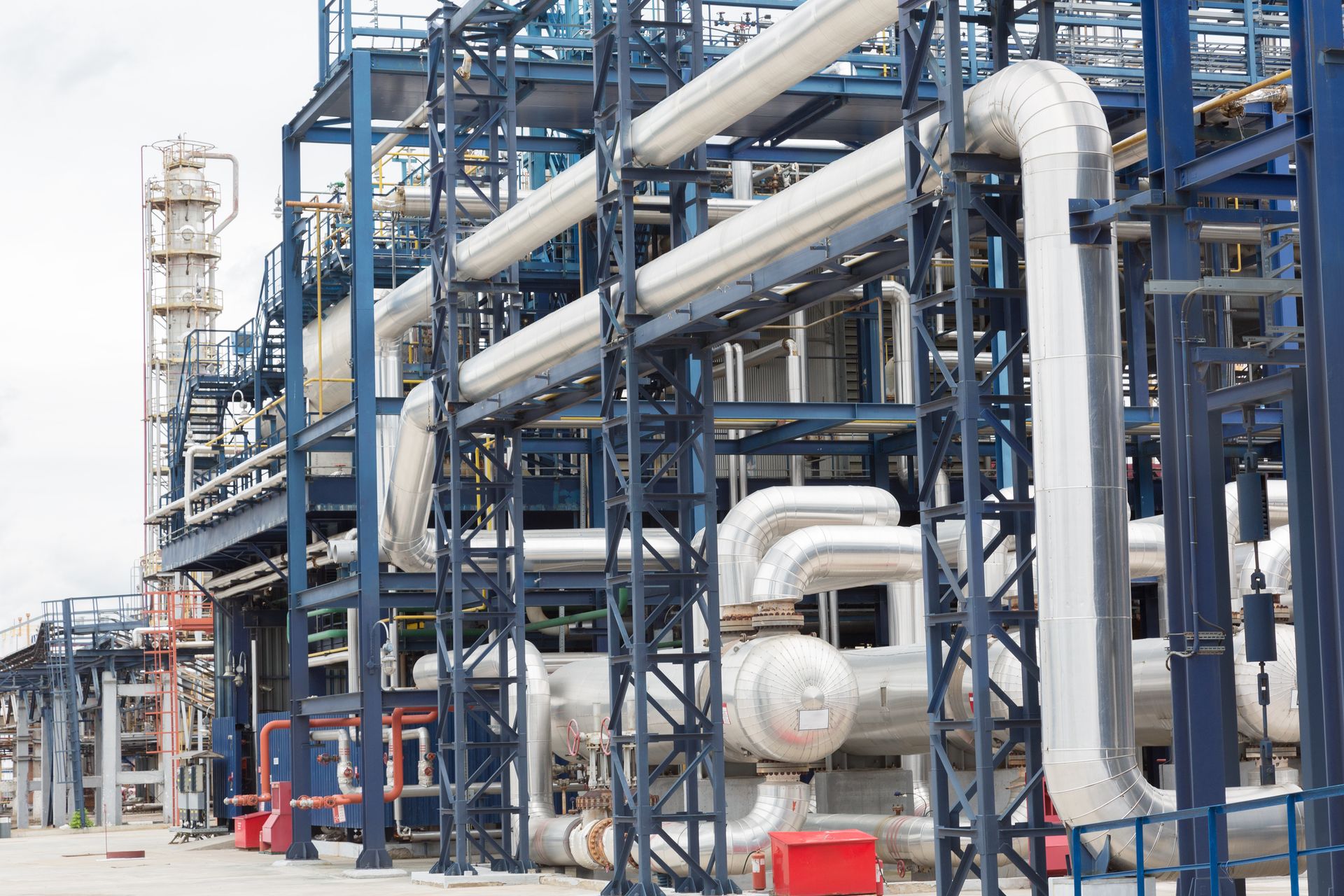
LNG storage and regasification, air separation cold boxes, liquid oxygen and nitrogen distribution, liquid hydrogen production and storage, and ammonia at low temperature all share one design problem and differ only in its severity.
Liquid hydrogen pushes it furthest: at 20 K the radiative path dominates, ordinary insulation families stop being candidates and the design moves to vacuum and multi-layer systems with measured performance rather than catalogue figures.
The governing criterion changes with the temperature and with the fluid. Each service is designed against the one that actually controls it.
Contraction over a 180 K range, barrier continuity and boil-off guarantee control the design.
Material compatibility and cleanliness for oxygen service override thermal optimisation.
Cold bridging at supports and air condensation on cold surfaces govern the detailing.
Radiation dominates; vacuum and multi-layer systems with measured conductivity are required.
Layer density, seams, penetrations and outgassing decide performance, not thickness.
Condensation control and vapour drive govern a system that is otherwise thermally undemanding.

Below roughly 1E-3 mbar the gaseous conduction path collapses and radiation takes over. Multi-layer insulation then performs according to reflector emissivity, layer density, seam treatment and penetration count, and not according to how thick the blanket is.
Layer density is the parameter most often got wrong. Compress the blanket and the solid conduction path between reflectors destroys the performance the layer count promised.

Since the company was founded we have never used a subcontractor on any job. Cryogenic work is carried out by our own qualified and certified personnel, with our own tools and equipment.
That matters more here than anywhere else: joint stagger, sealant coverage, barrier lap and handling damage are all decided by the crew, and none of them can be corrected once the cladding is closed.
Industrial Insulation Catalogue
Engineering scope, calculation and documentation services, material families and application capability in a single document.
ERATHERM works as an engineering partner for operators, EPC contractors and equipment manufacturers. Calculation, design, documentation and specification work is delivered remotely under the client's document control procedure; inspection, site supervision and application teams are mobilised to site.
It depends on which risk governs. Cellular glass is closed-cell, non-combustible and dimensionally stable, and is usually preferred where moisture ingress is the dominant risk. Aerogel blanket gives a much lower conductivity per millimetre and wins where space or weight is constrained, provided the vapour barrier strategy is sound. We compare both against the actual operating range and the available annulus.
Heat in-leak is summed path by path: through the insulation, through supports and saddles, through nozzles and instrument connections, and through penetrations. Each path is calculated separately, because in a well-insulated system the penetrations usually dominate.
Yes. Jacket interfaces, support standoffs, warm-to-cold transitions, pump-out ports and getter arrangement are designed as part of the heat leak budget, with the thermal shorts identified explicitly.
Yes. Chamber shroud insulation, MLI blanket design, seam and penetration treatment and outgassing limits are part of our defence and space work, carried out under non-disclosure agreements.
Fluid and operating temperature range, line and equipment list with sizes, ambient design conditions, available annulus or space constraint, any boil-off or surface temperature guarantee, and the project specification if one exists.
We can. Material supply is a separate package and includes export control screening, certification review and alternative sourcing where the first-choice family is not available in the project country.
The detailed pages behind each part of the design.
Send the fluid, the operating range, the line and equipment list and any boil-off or surface temperature requirement; we will define the design basis, the deliverables and the schedule.