
Noise survey and source ranking
Octave band measurement at the source and at the receiver, with the dominant paths identified so treatment is applied where it changes the result.

Noise limits are met or missed at the design stage, not at the commissioning survey. ERATHERM treats industrial noise control as an engineering problem with a measurable target: the dominant sources are identified and ranked, the required insertion loss is calculated, and acoustic lagging, enclosures, silencers and barriers are designed to reach it without compromising the thermal system underneath. We cover compressors, turbines, blowers, valves, piping, exhaust systems and process equipment, and we install what we design with our own crews. We work worldwide, in EPC-level English.

Each package below answers a different part of the problem. They can be taken separately, but the measurement at the start and the verification at the end are what make the rest defensible.
Octave band measurement at the source and at the receiver, with the dominant paths identified so treatment is applied where it changes the result.
Absorber, barrier mass and decoupling layer designed as a system, with the required insertion loss calculated per octave band rather than quoted as a single figure.
Panel construction, transmission loss, door and window detailing, ventilation openings and the access the maintenance team will actually need.
Exhaust, intake, vent and duct silencers sized against the pressure drop the process can tolerate, with baffle construction detailed for the temperature and the flow.
Where the equipment is hot, the acoustic and thermal systems are designed together, because a barrier layer added over a thermal system changes both performances.
Post-installation measurement against the design target, reported in the same octave bands as the original survey, with the shortfall located if there is one.
A treatment designed without a source measurement is a guess. Where no survey data exists we measure first, and the measurement report is a deliverable in its own right.

Acoustic lagging is not thicker thermal insulation. The porous layer absorbs, the mass layer blocks transmission, and the decoupling between them is what stops the two from acting as one stiff panel and short-circuiting the design.
Get the order or the decoupling wrong and the measured insertion loss collapses, even though every material in the build-up is correct on its own data sheet.
Produced under your document control procedure, in EPC-level English, revision controlled.
Octave band measurement, source ranking and dominant path identification.
Required insertion loss, build-up selection and predicted result per band.
Lagging build-ups, enclosure panels, door and penetration details, silencer arrangement.
Materials, workmanship, acceptance criteria and the measurement method for verification.
Quantities by system and area, with the acoustic and thermal layers itemised separately.
Post-installation measurement against target, with corrective scope if required.
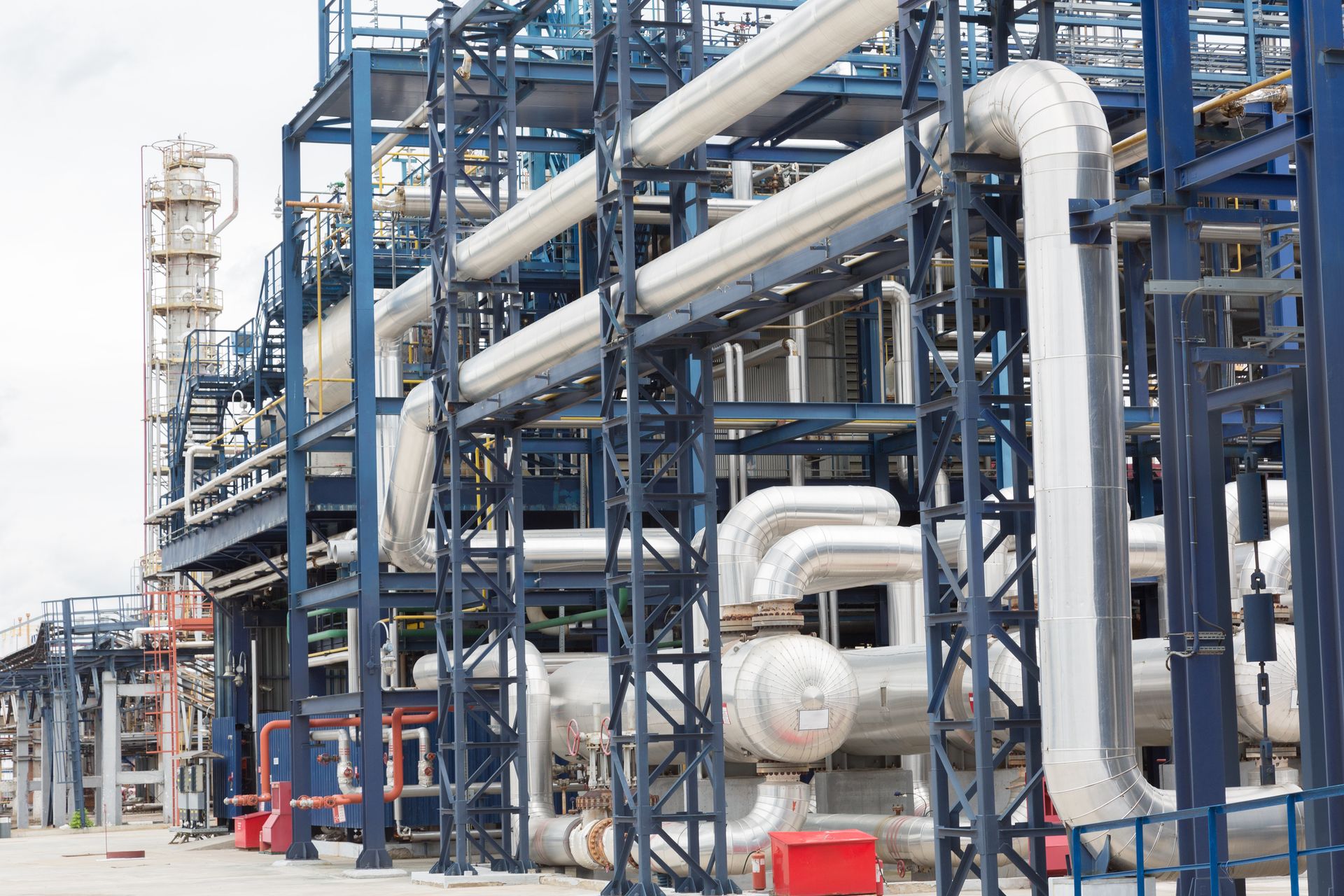
In most plants a small number of sources carry the result: compressors and their piping, gas and steam turbines, blowers and fans, control valves and the lines downstream of them, and exhaust and vent systems.
Valve-generated noise is the one most often treated in the wrong place. It is generated inside the pipe and radiated by the pipe wall for many metres downstream, so lagging only the valve body leaves most of the source untreated.
Noise control is a choice between treating the source, the path and the receiver. Each option below is appropriate to a different situation.
Pipe and equipment treatment where the radiating surface is the source and access must be retained.
Machine-level treatment where high insertion loss is required and ventilation can be designed in.
In-line treatment of exhaust, vent and intake noise where the path can be treated directly.
Partial treatment where line of sight to the receiver can be broken at lower cost.
Equipment requiring frequent access, treated without losing the acoustic or thermal performance.
Airborne and structure-borne treatment where signature and habitability requirements govern.

Adding a mass barrier and a second absorber layer over a hot line changes the thermal resistance, the surface temperature and the expansion behaviour of the whole build-up. A treatment designed only acoustically can push the surface temperature below the acid dew point or above the personnel protection limit.
We recalculate the thermal case for the combined system and detail the expansion and support arrangement for the increased thickness and weight.

Since the company was founded we have never used a subcontractor on any job. Acoustic work is carried out by our own qualified and certified personnel, with our own tools and equipment.
Acoustic performance is destroyed by small construction faults: an unsealed penetration, a rigid contact across the decoupling layer, a door that does not compress its seal. These are crew decisions, which is why we do not hand them to anyone else.
Industrial Insulation Catalogue
Engineering scope, calculation and documentation services, material families and application capability in a single document.
ERATHERM works as an engineering partner for operators, EPC contractors and equipment manufacturers. Calculation, design, documentation and specification work is delivered remotely under the client's document control procedure; inspection, site supervision and application teams are mobilised to site.
It depends on the frequency content and the build-up. A correctly designed absorber, barrier and decoupling system on piping commonly achieves a substantial reduction in the mid and high bands and much less at low frequency, which is why the target is set per octave band and not as a single dB(A) figure.
Because the noise is generated inside the pipe and radiated by the pipe wall downstream of the valve. Treating the valve body alone leaves the radiating surface untreated. The treated length is determined from the measurement, not from the valve dimensions.
Yes. An octave band survey before design and a verification measurement after installation are part of the standard package, reported in the same bands so the result can be compared directly with the target.
Yes, and on hot equipment they usually must be. The combined build-up is recalculated thermally, because adding mass and absorber layers changes surface temperature, dew point margin and expansion behaviour.
Yes. Access doors, removable panels, ventilation openings with their own silencers and lifting arrangements are designed into the enclosure. An enclosure that has to be cut open for maintenance does not stay acoustically intact for long.
Existing noise survey data if available, equipment list with operating conditions, the applicable limit and where it is measured, plant layout, and the thermal insulation scheme already in place or planned.
The detailed pages behind each part of the scope.
With the applicable noise limit, the survey data and the equipment list we will rank the sources, calculate the required insertion loss and define the treatment and its verification.