
Porous absorber layer
Mineral wool thickness and density chosen for the frequency range of the source, not for the thermal duty. Low frequency content needs depth that thermal design never asks for.

Acoustic lagging is a three-layer problem: a porous absorber, a limp mass barrier and a cladding that must not short-circuit the two. Thickness alone does not set insertion loss — the mass of the barrier and the integrity of the decoupling do — and a build-up that ignores that will miss its target at exactly the frequencies that matter.
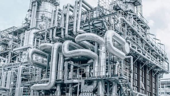
Each layer does one job. The commonest failure is a build-up where the cladding touches the pipe and carries sound straight past all three.
Mineral wool thickness and density chosen for the frequency range of the source, not for the thermal duty. Low frequency content needs depth that thermal design never asks for.
Surface mass sets the barrier performance. The layer is selected by weight per unit area and must stay decoupled from the pipe to work at all.
Fixings, banding and supports that touch both the pipe and the cladding bypass the whole build-up. These are detailed first, because no thickness recovers from them.
Published insertion loss data comes from laboratory tests on specific build-ups. We size from that data and state the installed derating we expect, rather than presenting a laboratory figure as a site guarantee.
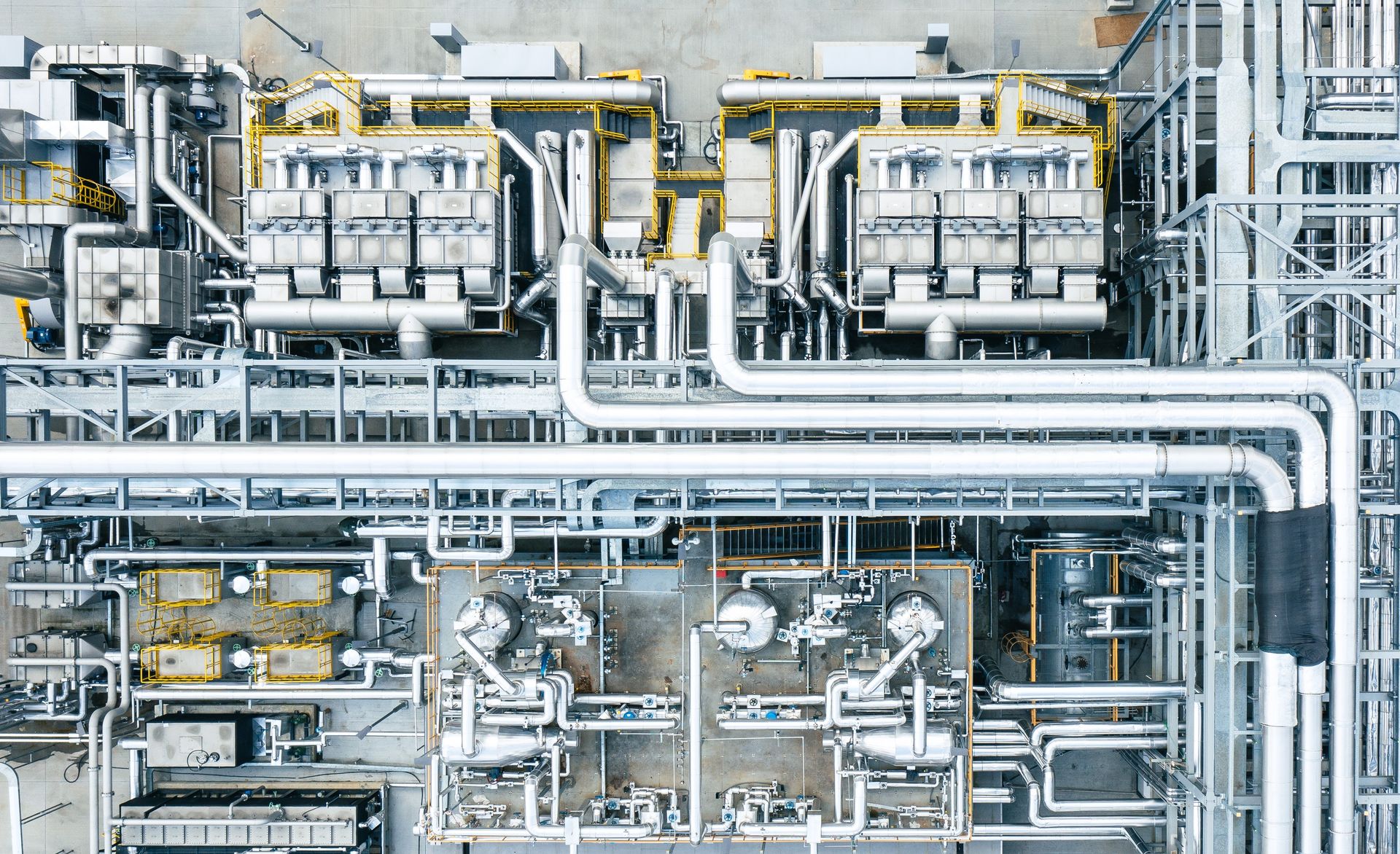
We start from the measured or predicted source spectrum and the target at the receiver, express the required insertion loss by octave band, and select a build-up whose tested performance exceeds the requirement across the governing bands with margin for installed derating.
The build-up drawing matters as much as the calculation, because this is a system that is routinely defeated during installation.
Source spectrum, target, required insertion loss by band and the selected build-up.
Layer by layer, with density, thickness and surface mass stated for each.
Supports, banding and terminations drawn so acoustic bridges cannot be introduced.
Where thermal and acoustic requirements coexist, the governing case for each line.
The steps where site practice most often defeats the design, called out explicitly.
What to measure after installation to confirm the design was achieved.
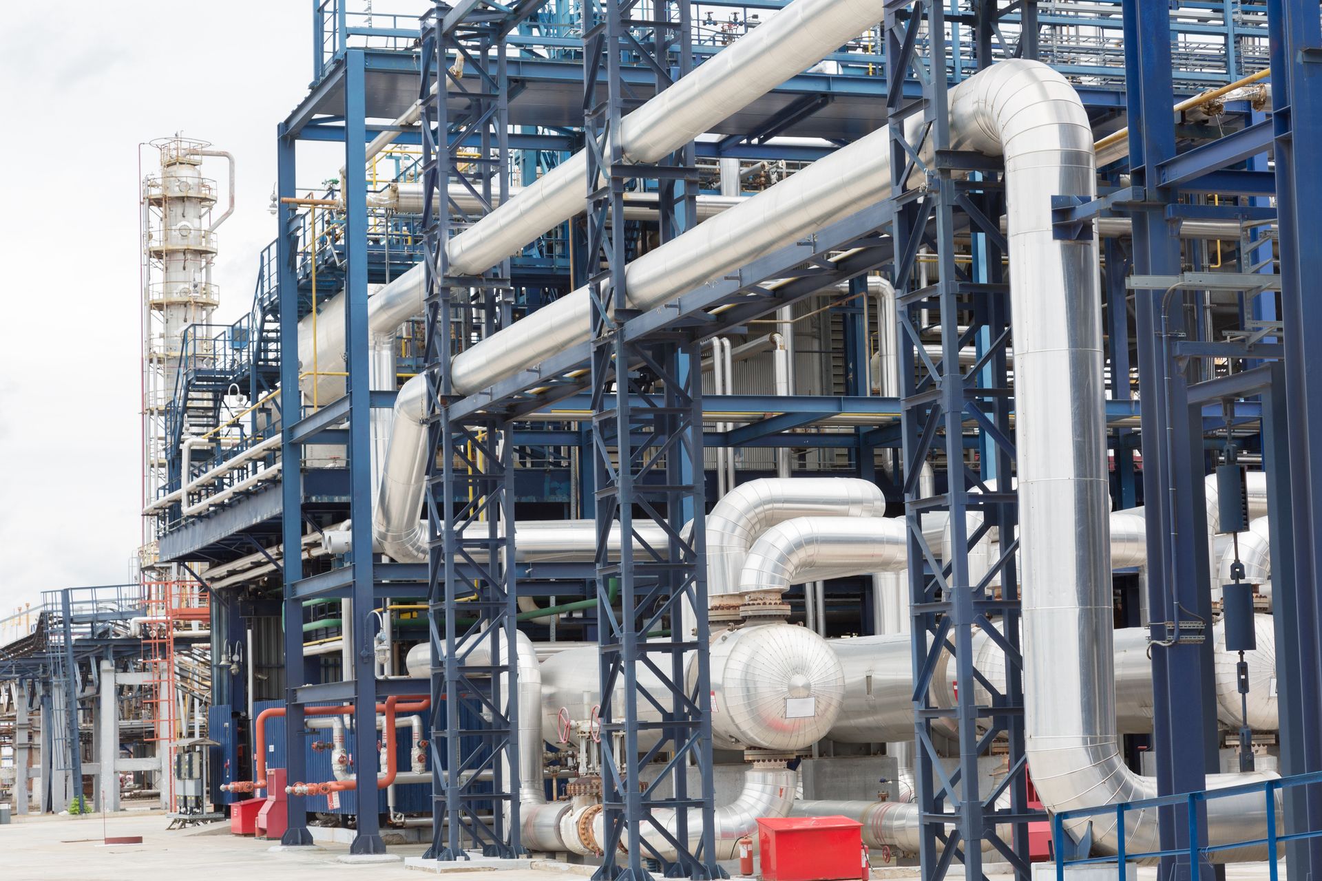
A thermal design wants low conductivity and minimal mass. An acoustic design wants depth for absorption and mass for transmission loss. Where both apply to the same line, one requirement governs the thickness and the other governs the layer selection, and the two have to be reconciled deliberately.
Industrial Insulation Catalogue
Engineering scope, calculation and documentation services, material families and application capability in a single document.
ERATHERM works as an engineering partner for operators, EPC contractors and equipment manufacturers. Calculation, design, documentation and specification work is delivered remotely under the client's document control procedure; inspection, site supervision and application teams are mobilised to site.
Because the same overall figure can come from very different spectra, and the build-up that solves a high frequency valve noise problem does almost nothing for low frequency flow noise. We ask for octave band data, or we measure it, before selecting anything.
No. Beyond the depth the absorber needs for the governing frequency, further thickness adds cost and weight with little acoustic return. Additional performance comes from barrier mass and from better decoupling, not from more wool.
Acoustic bridges. A banding strap, a support shoe or a cladding screw that contacts the pipe transmits sound past the entire build-up. Laboratory tests have no such bridges; real installations usually have several unless the detailing prevents them.
Yes, and we recommend it where a contractual noise limit applies. Measurement before and after, at agreed positions, is the only evidence that the design was achieved rather than the materials merely delivered.
Acoustic duty often sits alongside a thermal requirement on the same line.
Calculation and design
Insulation thickness calculation Condensation control calculation Freeze protection thickness Fire-rated insulation thickness Acoustic insulation thickness CO2 emission reduction calculationWe will convert the spectrum into a required insertion loss by band, select a build-up that meets it and detail the decoupling that keeps it working.